background image


Page 77 


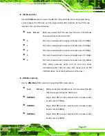
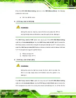
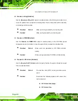
CPU Fan PWM Control [070] 

The 

CPU Fan PWM Control

 option can only be set if the 

CPU FAN Mode Setting

 option 

is set to 

Manual Mode

. Use the 

CPU Fan PWM Control

 option to select PWM duty cycle 

control. The PWM duty cycle specifies the width of the modulated pulse. A high value 

ensures a wide pulse and a low value ensures a narrow pulse. To select a value, select 

the 

CPU Fan PWM Control

 option and enter a decimal number between 000 and 127. 

The PWM Duty Cycle control range is specified below. 


PWM Minimum Mode: 0 


PWM Maximum Mode: 127 

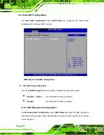
The following system parameters and values are shown. The system parameters that are 

monitored are: 


System Temperatures

: The following system temperatures are monitored 

o


CPU Temperature   

o


PWM Temperature 

o


System Temperature 


Fan Speeds

: The CPU cooling fan speed is monitored. 

o


CPU Fan1 Speed 

o


SYS_Fan1 Speed 

o


SYS_FAN2 Speed 


Voltages

: The following system voltages are monitored 

o


CPU Core 

o


+1.8V 

o


+3.30V 

o


+5.00V 

o


+12.0V 

o


+1.05V 

o


+1.5V 

o


+1.25V 

o


VBAT 

Summary of Contents for AFL-15C-9652

Page 1: ...Manual AFL 9652 series Flat Panel PC MODEL AFL 9652 Series All in one Flat Panel PC with Intel Core 2 Duo Celeron M Touch Screen 802 11 a b g n Wi Fi Bluetooth Two RJ 45 GbE IP 64 Protection and iAMT...

Page 2: ...Page II Revision Date Version Changes 2 October 2009 1 02 Added back cover screw torque warning 7 May 2009 1 01 Modified jumper setting information September 2008 1 00 Initial release...

Page 3: ...t of the use or inability to use the product or documentation even if advised of the possibility of such damages This document contains proprietary information protected by copyright All rights are re...

Page 4: ...ning messages may result in permanent damage to the AFL 9652 series or personal injury to the user Please take warning messages seriously CAUTION Cautionary messages should also be heeded to help redu...

Page 5: ...in can help avoid making mistakes Notes are easy to recognize The word note is written as NOTE both capitalized and bold and is followed by text The text is the cautionary message A note message is sh...

Page 6: ...ms listed below should all be included in the AFL 9652 series package 1 x Power cord 1 x Power adapter 1 x User Manual and driver CD 1 x Touch screen pen 1 x eSATA cable 1 x Screw kit 1 x Panel mounti...

Page 7: ...FICATIONS 10 2 1 DIMENSIONS 11 2 1 1 AFL 15C 9652 Dimensions 11 2 1 2 AFL 17C 9652 Dimensions 12 2 1 3 AFL 19C 9652 Dimensions 13 2 2 INTEL DESK TOP PROCESSOR SUPPORT 14 2 3 MOTHERBOARD COMPONENTS 15...

Page 8: ...r Connector 21 2 9 WIRELESS CONNECTIONS 22 2 9 1 USB Bluetooth Module 22 2 9 2 Wireless Ethernet 23 2 10 OPTIONAL MODULES 23 2 10 1 HSDPA Module Optional 23 2 10 2 GPRS Module Optional 23 3 UNPACKING...

Page 9: ...54 5 5 1 Clear CMOS Jumper J_CMOS1 55 5 5 2 COM1 RI and Voltage Select J10 55 5 5 3 COM3 RI and Voltage Select J10 55 5 5 4 COM3 Mode Select 56 5 5 4 1 COM3 RS 422 and RS 485 Pinouts 57 5 5 5 Compact...

Page 10: ...EXIT 103 7 SOFTWARE DRIVERS 105 7 1 AVAILABLE SOFTWARE DRIVERS 106 7 2 INTEL CHIPSET DRIVER 106 7 3 INTEL GRAPHICS MEDIAACCELERATOR DRIVER 111 7 4 INTEL 82566 GIGABIT LAN CONNECT DEVICE DRIVER 116 7 5...

Page 11: ...66 B 1 SAFETY PRECAUTIONS 167 B 1 1 General Safety Precautions 167 B 1 2 Anti static Precautions 168 B 2 MAINTENANCE AND CLEANING PRECAUTIONS 168 B 2 1 Maintenance and Cleaning 168 B 2 2 Cleaning Tool...

Page 12: ...re 2 6 COM Ports 16 Figure 2 7 RJ 45 Ethernet Connectors 17 Figure 2 8 External USB Ports 17 Figure 2 9 eSATA Connector 17 Figure 2 10 LCD Screen 18 Figure 2 11 VGA Connector 19 Figure 2 12 Audio Jack...

Page 13: ...5 Figure 4 20 Install into a Rack Cabinet 45 Figure 4 21 LAN Connection 46 Figure 4 22 Serial Device Connector 47 Figure 4 23 USB Device Connection 48 Figure 4 24 VGA Connector 49 Figure 5 1 Aluminum...

Page 14: ...river Installation Ready Window 122 Figure 7 26 Intel 82566 Driver Installation Progress 123 Figure 7 27 Intel 82573 Driver Directory Icon 124 Figure 7 28 Intel 82573 Operating System 125 Figure 7 29...

Page 15: ...Matrix Storage Manager License Agreement 142 Figure 7 57 Matrix Storage Manager Readme File 143 Figure 7 58 Matrix Storage Manager Setup Complete 144 Figure 7 59 IAMT Driver Directory 145 Figure 7 60...

Page 16: ...re 8 9 Enable Network Interface 155 Figure 8 10 Exit 156 Figure 8 11 Intel AMT Web Address 157 Figure 8 12 Intel AMT Web Login Dialog 158 Figure 8 13 Intel AMT Web Interface 159 Figure 8 14 Wireless L...

Page 17: ...RS 422 485 Selection 56 Table 5 5 COM3 Mode Selection 56 Table 5 6 COM3 Mode Selection 56 Table 5 7 RS 422 Pinouts 57 Table 5 8 RS 485 Pinouts 57 Table 5 9 CompactFlash Master Slave Selection 57 Table...

Page 18: ......

Page 19: ...Page 1 1 Introduction Chapter 1...

Page 20: ...with an Intel ICH8M input output controller hub ensures optimal memory graphics and peripheral I O support The system comes with 1 0 GB or 2 0 GB of preinstalled DDR2 SDRAM and supports a maximum of 4...

Page 21: ...17 300 cd m2 1 GB DDR2 Yes T7500 WT R 2GB 2 2 GHz Intel Core 2 Duo T7500 17 300 cd m2 2 GB DDR2 Yes AFL 19C 9652 CPU LCD Brightness Memory Wireless CM550 WT R 1GB 2 0 GHz Intel Celeron M 550 19 300 cd...

Page 22: ...ed in an aluminum chassis An ABS PC plastic cover surrounds the aluminum chassis VESA compliant screw holes in the rear panel allow the AFOLUX to be attached to any VESA compliant mounting The access...

Page 23: ...ottom Panel The bottom panel of the AFL 9652 series has the following I O interfaces Figure 1 4 1 x 12 V DC power input connector 1 x Audio jack 1 x AT ATX switch 1 x eSATA port 1 x Power switch 1 x R...

Page 24: ...Overview The AFL 9652 includes the following parts inside the aluminum internal cover 1 0 GB DDR2 SO DIMM Antennas Backlight inverter Bluetooth module CompactFlash disk optional GPRS module optional...

Page 25: ...l PC has the following preinstalled components 1 x Motherboard 1 x TFT LCD screen 1 x Touch screen panel 1 x Inverter 1 x Wireless LAN module 2 x DDR2 memory modules 1 x Bluetooth module 1 x AT ATX sw...

Page 26: ...178 Backlight MTBF 50 000 hours SBC Model AFLMB 9652 CPU 2 0 GHz Intel Celeron M 550 CPU or 2 20 GHz Intel Core 2 Duo T7500 CPU Memory One or two 200 pin 1 0 GB dual channel DDR2 SO DIMM I O Ports 1...

Page 27: ...0 C 45 C with CompactFlash or SSD HDD Storage Temperature 20 C 60 C Net Weight 5 8 kg 5 8 kg 6 2 kg IP Level IP 64 EMC CE FCC CCC Safety UL CB Touch Screen Resistive Type 5 Wire touch controller IC is...

Page 28: ...Page 10 2 Specifications Chapter 2...

Page 29: ...Page 11 2 1 Dimensions 2 1 1 AFL 15C 9652 Dimensions The dimensions of the AFL 15C 9652 flat panel PC are shown in Figure 2 1 below Figure 2 1 AFL 15C 9652 Dimensions units in mm...

Page 30: ...Page 12 2 1 2 AFL 17C 9652 Dimensions The dimensions of the AFL 17C 9652 flat panel PC are shown in Figure 2 2 below e SATA Figure 2 2 AFL 17C 9652 Dimensions units in mm...

Page 31: ...Page 13 2 1 3 AFL 19C 9652 Dimensions The dimensions of the AFL 19C 9652 flat panel PC are shown in Figure 2 2 below Figure 2 3 AFL 19C 9652 Dimensions units in mm...

Page 32: ...ide bus FSB and a 4 0 MB L2 cache The 550 Intel Celeron M processor has a CPU speed of 2 0 GHz a 533 MHz front side bus FSB and a 1 0 MB L2 cache The processor is shown in Figure 2 4 below Figure 2 4...

Page 33: ...rnal motherboard Figure 2 5 Memory Module and Memory Socket 2 3 1 2 Additional Memory The Intel GME965 is capable of supporting two 200 pin 2 0 GB max 400 MHz DDR2 SDRAM SO DIMM system max 4 0 GB If a...

Page 34: ...be designated as a 5 V or 12 V power supply The two serial ports COM1 and COM3 are interfaced to the ITE IT8712 super IO through the low pin count LPC bus to the ICH8M Southbridge Figure 2 6 COM Ports...

Page 35: ...nnectors are all fully compliant with USB specification Revision 2 0 and USB specification Revision 1 1 and can be interfaced to both USB 1 1 and USB 2 0 compliant devices Figure 2 8 External USB Port...

Page 36: ...oller for the 5 wire resistive touch screen is installed on the motherboard The sensitive touch screen is accurate reliable and durable 2 6 Graphics 2 6 1 Intel GME965 Integrated Graphics Media Accele...

Page 37: ...thbridge is integrated to a RealTek ALC262 audio codec The RealTek ALC262 is connected to the external audio jack which is then connected to compliant audio devices The RealTek ALC262 is a four channe...

Page 38: ...mode selected the AFOLUX AFL 9652 panel PC goes in a standby mode when it is turned off The panel PC can be easily turned on via network or a power switch in standby mode Remote power control is perfe...

Page 39: ...ent center and other applications including ATM Self service kiosk Plant environment monitoring system Factory automation platform Manufacturing shop flow 2 8 2 Power Adapter The system is shipped wit...

Page 40: ...The AFL 9652 Bluetooth module enables wireless communications between the AFL 9652 and various peripheral devices through a Bluetooth network The peripheral devices may include Headsets Barcode reader...

Page 41: ...lowing sections describe the optional module available to the user 2 10 1 HSDPA Module Optional An optional HSDPA module can be integrated into the AFL 9652 and provide the 3 5G mobile connectivity Th...

Page 42: ...Page 24 3 Unpacking Chapter 3...

Page 43: ...or a sharp pair of scissors that seals the top side of the external second box Step 2 Open the external second box Step 3 Use box cutters a knife or a sharp pair of scissors that seals the top side of...

Page 44: ...26 Quantity Item Image Standard 1 AFL 9652 series panel PC 1 Power adapter 1 Power cord 1 User manual CD and driver CD 1 Touch pen 1 eSATA cable 1 Screw kit Optional Wall mounting kit Panel mounting...

Page 45: ...with Windows CE 5 0 pre installed 128 MB CompactFlash card with Windows CE 6 0 pre installed 1 GB CompactFlash card with Windows XPE pre installed If any of these items are missing or damaged contact...

Page 46: ...Page 28 4 Installation Chapter 4...

Page 47: ...ny grounded conducting material During the time the board is handled frequently touch any conducting materials that are connected to the ground Use an anti static pad When configuring the AFL 9652 pla...

Page 48: ...esistive type touch screen panel Wireless LAN module Bluetooth module AT ATX power switch Preinstalled OEM customizations may include the following Different DDR2 memory modules 2 5 SATA hard disk dri...

Page 49: ...lash Type I II slot inside the left side panel To install the CF card follow the instructions below Step 1 Remove the retention screws Figure 4 1 and lift the cover off the flat panel PC Figure 4 1 Ba...

Page 50: ...ews will crack the plastic frame Maximum torque for cover screws is 5 kg cm 0 36 lb ft 0 49 Nm 4 6 HDD Installation To install the hard drive please follow the steps below Step 1 Disconnect the system...

Page 51: ...um cover to remove Step 5 Remove the system fan on the top of the HDD bracket by removing the two retention screws Figure 4 5 Figure 4 5 System Fan Retention Screws Step 6 Remove the remaining two HDD...

Page 52: ...n the hard drive bracket Fasten four flat head retention screws to secure the hard drive to the bracket Figure 4 7 Figure 4 7 Hard Drive Retention Screws Step 8 Reinstall the hard drive bracket Slide...

Page 53: ...e through an AT ATX switch on the bottom panel Figure 4 9 To select AT mode or ATX mode follow the steps below Step 1 Locate the AT ATX switch on the bottom panel Figure 4 9 Figure 4 9 AT ATX Switch L...

Page 54: ...panel PC onto an arm onto the wall or onto a panel it is better to have more than one person to help with the installation to make sure the panel PC does not fall down and get damaged The four method...

Page 55: ...re 4 10 Wall mounting Bracket Step 6 Insert the four monitor mounting screws provided in the wall mounting kit into the four screw holes on the real panel of the flat panel PC and tighten until the sc...

Page 56: ...ure 4 11 Chassis Support Screws NOTE In the diagram below the bracket is already installed on the wall Step 9 Secure the panel PC by fastening the retention screw of the wall mounting bracket Figure 4...

Page 57: ...to mount the flat panel PC Step 2 Cut out a section from the panel that corresponds to the rear panel dimensions of the flat panel PC Take care that the panel section that is cut out is smaller than...

Page 58: ...Page 40 Figure 4 13 AFL 15C 9652 Cutout Dimensions units in mm Figure 4 14 AFL 17C 9652 Cutout Dimensions units in mm...

Page 59: ...frame is flush against the panel Step 4 Insert the panel mounting clamps into the pre formed holes along the edges of the chassis behind the plastic frame Step 5 Tighten the screws that pass through t...

Page 60: ...arm please follow the steps below Step 1 The arm is a separately purchased item Please correctly mount the arm onto the surface it uses as a base To do this refer to the installation documentation th...

Page 61: ...gure 4 17 Figure 4 17 Arm Mounting Retention Screw Holes Step 4 Secure the flat panel PC to the interface pad by inserting four retention screws through the bottom of the mounting arm interface pad an...

Page 62: ...el PC through the rack cabinet bracket until the plastic frame is flush against the front of the bracket Figure 4 18 Figure 4 18 The Rack Cabinet Bracket Step 2 Insert the rack mounting clamps into th...

Page 63: ...Page 45 Figure 4 19 Secure the Rack Cabinet Bracket Step 4 Slide the flat panel PC with the attached rack cabinet bracket into a rack or cabinet Figure 4 20 Figure 4 20 Install into a Rack Cabinet...

Page 64: ...ttom of the rear panel on the AFL 9652 panel PC 4 9 1 LAN Connection There are two external RJ 45 LAN connectors The RJ 45 connectors enable connection to an external network To connect a LAN cable wi...

Page 65: ...elow to connect a serial device to the AFL 9652 Series panel PC Step 1 Locate the DB 9 connector The location of the DB 9 connector is shown in Chapter 2 Step 2 Insert the serial connector Insert the...

Page 66: ...e instructions below Step 1 Locate the USB connectors The locations of the USB connectors are shown in Chapter 2 Step 2 Align the connectors Align the USB device connector with one of the connectors o...

Page 67: ...apter 3 Step 2 Align the VGA connector Align the male DB 15 connector on the VGA screen cable with the female DB 15 connector on the external peripheral interface Step 3 Insert the VGA connector Once...

Page 68: ...Page 50 5 System Maintenance Chapter 5...

Page 69: ...he system vendor reseller or an IEI sales person directly 5 3 Internal Aluminum Cover Removal WARNING Turn the power off before removing the back cover Failing to do so may lead to severe damage of AF...

Page 70: ...w Remove the following screws 2 x Flat head screws 8 x Round head screws Screw positions are indicated below Figure 5 1 Figure 5 1 Aluminum Back Cover Retention Screws 5 4 Memory Module Replacement Th...

Page 71: ...asp the DDR2 memory module by the edges and carefully pull it out of the socket Step 6 Install the new DDR2 memory module by pushing it into the socket at an angle Figure 5 3 Step 7 Gently pull the sp...

Page 72: ...tic cover that slides over the pins to connect them To CLOSE SHORT a jumper means connecting the pins of the jumper with the plastic clip and to OPEN a jumper means removing the plastic clip from a ju...

Page 73: ...Clear CMOS Jumper Settings 5 5 2 COM1 RI and Voltage Select J10 The COM1 pin 9 signal can be selected as 12V 5V or Ring J10 Description 7 9 Use for RI 3 5 5 V 1 3 12 V Table 5 2 COM1 RI and Voltage Se...

Page 74: ...TX 4 6 RS 485 D Table 5 4 COM3 RS 422 485 Selection J8 Description Short 1 2 DCD3 RS 232 Short 2 3 TX3 RS 422 485 Short 4 5 RXD3 RS 232 Short 5 6 TX3 RS 422 485 Short 7 8 DSR3 RS 232 Short 8 9 RX3 RS...

Page 75: ...e 5 7 RS 422 Pinouts COM 3 RS 485 Description Pin 1 Data Pin 2 Data Table 5 8 RS 485 Pinouts 5 5 5 CompactFlash Setup J4 The Master Slave selection allows the CompactFlash slot to be setup as either t...

Page 76: ...Page 58 6 AMI BIOS Setup Chapter 6...

Page 77: ...on the screen 0 If the message disappears before the DELETE key is pressed restart the computer and try again 6 1 2 Using Setup Use the arrow keys to highlight items press ENTER to select use the Pag...

Page 78: ...e computer cannot boot after changes to the system configuration is made CMOS defaults Use the jumper described in Chapter 5 or disconnect the battery from the connector 6 1 5 BIOS Menu Bar The menu b...

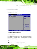
Page 79: ...s in System Overview cannot be changed The items shown in the system overview include AMI BIOS Displays auto detected BIOS information o Version Current BIOS version o Build Date Date the current BIOS...

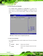
Page 80: ...CPU and peripheral devices through the following sub menus WARNING Setting the wrong values in the sections below may cause the system to malfunction Make sure that the settings made are compatible w...

Page 81: ...Page 63 BIOS Menu 2 Advanced 6 3 1 CPU Configuration Use the CPU Configuration menu BIOS Menu 3 to view detailed CPU specifications and configure the CPU...

Page 82: ...processing speed FSB Speed Lists the FSB speed Cache L1 Lists the CPU L1 cache size Cache L2 Lists the CPU L2 cache size Intel R SpeedStep tm tech Enabled Use the Intel R SpeedStep tm tech option to e...

Page 83: ...s option to configure the ATA IDE controller Disabled Disables the on board ATA IDE controller Compatible DEFAULT Configures the on board ATA IDE controller to be in compatible mode In this mode a SAT...

Page 84: ...ary IDE Slave Secondary IDE Master Secondary IDE Slave Third IDE Master Third IDE Slave Fourth IDE Master Fourth IDE Slave The IDE Configuration menu BIOS Menu 4 allows changes to the configurations f...

Page 85: ...S is prevented from searching for an IDE disk drive on the specified channel Auto DEFAULT The BIOS auto detects the IDE disk drive type attached to the specified channel This setting should be used if...

Page 86: ...g the LBA mode control on the specified channel Auto DEFAULT BIOS auto detects the LBA mode control on the specified channel Block Multi Sector Transfer Auto Use the Block Multi Sector Transfer to dis...

Page 87: ...mode 3 selected with a maximum transfer rate of 11 1MBps 4 PIO mode 4 selected with a maximum transfer rate of 16 6MBps This setting generally works with all hard disk drives manufactured after 1999 F...

Page 88: ...DMA mode 3 selected with a maximum data transfer rate of 44MBps To use this mode it is required that an 80 conductor ATA cable is used UDMA4 Ultra DMA mode 4 selected with a maximum data transfer rate...

Page 89: ...nsfer BIOS option to enables or disable 32 bit data transfers Disabled Prevents the BIOS from using 32 bit data transfers Enabled DEFAULT Allows BIOS to use 32 bit data transfers on supported hard dis...

Page 90: ...3 Serial Port2 Address 2F8 IRQ3 Use the Serial Port2 Address option to select the Serial Port 2 base address Disabled No base address is assigned to Serial Port 2 2F8 IRQ3 DEFAULT Serial Port 2 I O po...

Page 91: ...nterrupt address for serial port 4 Disabled No base address is assigned to serial port 3 3F8 Serial port 4 I O port address is 3F8 2F8 Serial port 4 I O port address is 2F8 3E8 Serial port 4 I O port...

Page 92: ...Mode DEFAULT Fan is on all the time Automatic mode Fan is off when the temperature is low enough Parameters must be set by the user PWM Manual mode Pulse width modulation set manually When the CPU FAN...

Page 93: ...ture at which the cooling fan should automatically turn off To select a value select the CPU Temp Limit of OFF option and enter a decimal number between 000 and 127 The temperature range is specified...

Page 94: ...mode the fan starts to rotate with after the temperature specified in the Temperature 3 Limit of Start is exceeded The Super I O chipset supports 128 PWM modes To select a value select the Fan 3 Start...

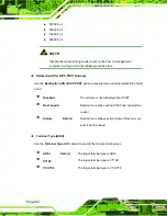
Page 95: ...ion and enter a decimal number between 000 and 127 The PWM Duty Cycle control range is specified below PWM Minimum Mode 0 PWM Maximum Mode 127 The following system parameters and values are shown The...

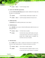
Page 96: ...upport Disabled Use the Intel AMT Support option to enable or disable the Intel AMT support Disabled DEFAULT The Intel AMT function is disabled Enabled The Intel AMT function is enabled 6 3 5 1 ME Sub...

Page 97: ...enable or disable HECI message when booting up the system Disabled The HECI message is disabled when booting up the system Enabled DEFAULT The HECI message is enabled when booting up the system HECI...

Page 98: ...or disable the IDE Redirection IDE R function on an AMT capable system Disabled DEFAULT The IDE R function is disabled Enabled The IDE R function allows an AMT capable client system to access IDE dev...

Page 99: ...e Intel Robson Technology option to be configured BIOS Menu 10 Intel Robson Configuration Intel Robson Disabled Use the Intel Robson BIOS option to enable or disable the Intel Robson Technology featur...

Page 100: ...eature and allows a remote host running a terminal program to display and configure the BIOS settings BIOS Menu 11 Remote Access Configuration Advanced Remote Access Disabled Use the Remote Access opt...

Page 101: ...stem is remotely accessed through COM3 COM4 System is remotely accessed through COM4 COM5 System is remotely accessed through COM5 NOTE Make sure the selected COM port is enabled through the Super I O...

Page 102: ...ify when console redirection should occur Disabled The console is not redirected after POST Boot Loader Redirection is active during POST and during Boot Loader Always DEFAULT Redirection is always ac...

Page 103: ...ation USB Configuration The USB Configuration field shows the system USB configuration The items listed are Module Version x xxxxx xxxxx USB Devices Enabled The USB Devices Enabled field lists the USB...

Page 104: ...es not become available until a USB compatible operating system is fully booted with all USB drivers loaded When this option is enabled any attached USB mouse or USB keyboard can control the system ev...

Page 105: ...enu 13 configures the Advanced Configuration and Power Interface ACPI and Power Management APM options BIOS Menu 13 Power Configuration 6 3 9 1 ACPI Configuration The ACPI Configuration menu BIOS Menu...

Page 106: ...POS DEFAULT The system enters S1 POS sleep state The system appears off The CPU is stopped RAM is refreshed the system is running in a low power mode S3 STR System appears off The CPU has no power RAM...

Page 107: ...s either turned on or off Suspend When the power button is pressed the system goes into suspend mode Restore on AC Power Loss Last State Use the Restore on AC Power Loss BIOS option to specify what st...

Page 108: ...bled Use the Resume on PME BIOS option to enable activity on the PCI PME power management event controller to rouse the system from a suspend or standby state Disabled DEFAULT Wake event not generated...

Page 109: ...ed by activity on the keyboard or mouse Enabled Wake event generated by activity on the keyboard or mouse Resume on PCI Express WAKE Enabled The Resume on PCI Express WAKE BIOS option specifies if the...

Page 110: ...to specify what IRQs can be assigned to a particular peripheral device Available The specified IRQ is available to be used by PCI PnP devices Reserved The specified IRQ is reserved for use by Legacy I...

Page 111: ...ied DMA is reserved for use by Legacy ISA devices Available DMA Channels are DM Channel 0 DM Channel 1 DM Channel 3 DM Channel 5 DM Channel 6 DM Channel 7 Reserved Memory Size Disabled Use the Reserve...

Page 112: ...OS Menu 17 Boot GbE LAN Boot 82566MM Disabled Use the GbE LAN Boot 82566MM option to enable the Intel 82566MM GbE controller to boot the system Enabled Can be booted from a remote system through the I...

Page 113: ...isabled DEFAULT Cannot be booted from a remote system through the Intel 82573L PCIe GbE controller Enabled Can be booted from a remote system through the Intel 82573L PCIe GbE controller 6 5 1 Boot Se...

Page 114: ...led OEM Logo displayed instead of POST messages AddOn ROM Display Mode Force BIOS Use the AddOn ROM Display Mode option to allow add on ROM read only memory messages to be displayed Force BIOS DEFAULT...

Page 115: ...nabled automatically when the computer system boots up This allows the immediate use of the 10 key numeric keypad located on the right side of the keyboard To confirm this the Number Lock LED light on...

Page 116: ...ption is Not Installed If a supervisor password must be installed select this field and enter the password After the password has been added Install appears next to Change Supervisor Password Change U...

Page 117: ...ation menus WARNING Setting the wrong values for the Chipset BIOS selections in the Chipset BIOS menu may cause the system to malfunction BIOS Menu 21 Chipset Configuration 6 7 1 North Bridge Configur...

Page 118: ...memory cannot be remapped Memory Hole Disabled Use the Memory Hole option to reserve memory space between 15MB and 16MB for ISA expansion cards that require a specified area of memory to work properl...

Page 119: ...B of memory used by internal graphics device Boot Display Device Auto Use the Display Device Select BIOS feature to determine what displays are used Dual display functionality is enabled here Dual dis...

Page 120: ...abled Use the HDA Controller option to enable the Southbridge high definition audio controller If the HDA device has been connected to the system this option should be enabled Enabled DEFAULT Southbri...

Page 121: ...d and can communicate with a remote management server 6 8 Exit Use the Exit menu BIOS Menu 24 to load default BIOS values optimal failsafe values and to save configuration changes BIOS Menu 24 Exit Sa...

Page 122: ...rd the changes and remain in the BIOS configuration setup program Load Optimal Defaults Use the Load Optimal Defaults option to load the optimal default values for each of the parameters on the Setup...

Page 123: ...Page 105 Chapter 7 7 Software Drivers...

Page 124: ...for the latest updates The following drivers can be installed on the system Intel chipset driver VGA driver LAN drivers Audio driver SATA driver Intel Active Management Technology AMT driver Installa...

Page 125: ...Page 107 Figure 7 1 Intel Chipset Driver Directory Step 3 Click on the directory icon in Figure 7 1 Step 4 The window in Figure 7 2 appears Figure 7 2 Intel Chipset Driver Setup Icon...

Page 126: ...on the infinst_autol setup icon in Figure 7 2 Step 6 The Intel Package Manager begins to extract the installation files See Figure 7 3 Figure 7 3 Intel Package Manager Step 7 The Intel Setup Welcome...

Page 127: ...e 7 4 Intel Setup Welcome Screen Step 8 Click NEXT to continue Step 9 The Intel license agreement in appears Figure 7 5 Intel Chipset Driver License Agreement Step 10 Accept the terms and conditions b...

Page 128: ...eadme file in Figure 7 6 appears Figure 7 6 Readme File Step 12 Click NEXT to continue Step 13 The driver is then installed Step 14 When the installation process is complete the Setup Complete screen...

Page 129: ...Step 15 To complete the chipset driver installation click FINISH Step 0 7 3 Intel Graphics Media Accelerator Driver To install the chipset driver please follow the steps below Step 1 Select the VGA dr...

Page 130: ...Page 112 Figure 7 8 Select the Operating System Step 3 Select the operating system from those shown in Figure 7 8 Step 4 A new window appears See Figure 7 9 Figure 7 9 Intel Driver Directory...

Page 131: ...icon in Figure 7 9 Step 6 A new window appears See Figure 7 10 Figure 7 10 Intel VGA Driver Setup Icon Step 7 Click on the VGA driver installation icon in See Figure 7 10 Step 8 The Readme informatio...

Page 132: ...ge 114 Figure 7 11 GMA Driver Readme File Step 9 Click NEXT to extract the GMA driver files See Figure 7 12 Figure 7 12 GMA Driver File Extraction Step 10 The welcome screen shown in Figure 7 13 appea...

Page 133: ...er Installation Welcome Screen Step 11 To continue the installation process click NEXT Step 12 The license agreement in Figure 7 14 appears Figure 7 14 GMA Driver License Agreement Step 13 Click the Y...

Page 134: ...ppears Figure 7 16 GMA Driver Installation Complete Step 16 After selecting when to restart the computer in Figure 7 16 click FINISH Step 0 7 4 Intel 82566 Gigabit LAN Connect Device Driver To install...

Page 135: ...Page 117 Figure 7 17 Intel 82566 Driver Directory Icon Step 3 Click on the Intel 82566DM MM directory icon in Figure 7 17 Step 4 The window in Figure 7 18 appears...

Page 136: ...Figure 7 18 Intel 82566 Operating System Step 5 Select the Operating System in Figure 7 18 Step 6 The window in Figure 7 19appears Step 7 In Figure 7 19 select the operating system type installed on t...

Page 137: ...Page 119 Figure 7 19 Select Operating System Type Step 8 The window in Figure 7 20 appears Figure 7 20 Driver Directory Step 9 Click on the directory icon in Figure 7 20...

Page 138: ...e Figure 7 21 Figure 7 21 Intel 82566 Device Driver Startup Icon Step 11 Double click the Intel 82566 driver startup icon in Figure 7 21 Step 12 The driver begins to extract the installation files Ste...

Page 139: ...n Step 15 The license agreement in Figure 7 23 appears Figure 7 23 Intel 82566 Driver License Agreement Step 16 Accept the conditions of the license agreement and click NEXT to continue Step 17 The Se...

Page 140: ...n configuration in Figure 7 24 and click NEXT to continue Step 19 The Ready to Install the Program window in Figure 7 25 appears Figure 7 25 Intel 82566 Driver Installation Ready Window Step 20 Click...

Page 141: ...ation is finished Click FINISH in the termination screen Step 0 7 5 Intel 82573 PCI Express Gigabit Ethernet Controller Driver To install the Intel 82573 PCIe GbE controller please follow the steps be...

Page 142: ...Page 124 Figure 7 27 Intel 82573 Driver Directory Icon Step 3 Click on the Intel 82573L directory icon in Figure 7 27 Step 4 The window in Figure 7 28 appears...

Page 143: ...igure 7 28 Intel 82573 Operating System Step 5 Select the Operating System in Figure 7 28 Step 6 The window in Figure 7 29 appears Step 7 In Figure 7 29 select the operating system type installed on t...

Page 144: ...Page 126 Figure 7 29 Select Operating System Type Step 8 The window in Figure 7 30 appears Figure 7 30 Driver Directory Step 9 Click on the directory icon in Figure 7 20...

Page 145: ...aining the Intel 82573 driver startup icon appears See Figure 7 30 Figure 7 31 Intel 82573 Driver Startup Icon Step 11 Click the startup icon in Figure 7 31 Step 12 The License Agreement for the Intel...

Page 146: ...eement Step 13 Accept the license terms and agreements in and click NEXT to continue Step 14 Next select the directory in which the files must be saved See Figure 7 33 Figure 7 33 Intel 82573 File Loc...

Page 147: ...tallation files See Figure 7 34 Figure 7 34 Intel 82573 Installation Files Extraction Step 17 The Intel PRO Network Connections window appears See Figure 7 35 Figure 7 35 Intel PRO Network Connections...

Page 148: ...Figure 7 36 appears Figure 7 36 Intel PRO Network Connections Welcome Step 20 Click NEXT to continue Step 21 A new License Agreement appears See Figure 7 37 Figure 7 37 License Agreement Step 22 Accep...

Page 149: ...38 Setup Type Step 24 Select the setup type in Figure 7 38 and click NEXT to continue Step 25 The drivers are installed See Figure 7 39 Figure 7 39 Intel 82573 Driver Installation Progress Step 26 Whe...

Page 150: ...led 7 6 1 BIOS Setup Step 1 Enter the BIOS setup To do this reboot the system and press DEL during POST Step 2 Go to the Southbridge Configuration menu Enable the High Definition Audio controller Step...

Page 151: ...Page 133 Figure 7 40 Select the Audio CODEC Step 3 Double click the ALC883 folder Step 4 Double click the appropriate operating system folder Figure 7 41...

Page 152: ...134 Figure 7 41 Select the OS Step 5 Double click the appropriate operating system version folder Figure 7 42 Figure 7 42 Select the OS Version Step 6 Double click the Setup exe program icon in Figure...

Page 153: ...e the Setup Program Icon Step 7 The InstallShield Wizard starts Figure 7 44 Figure 7 44 The InstallShield Wizard Starts Step 8 The InstallShield Wizard is prepared to guide the user through the rest o...

Page 154: ...nce initialized the InstallShield Wizard welcome screen appears Figure 7 46 Figure 7 46 InstallShield Wizard Welcome Screen Step 10 Click NEXT to continue the installation Step 11 InstallShield starts...

Page 155: ...e Configuration Step 12 The Installation Wizard updates the system as shown in Figure 7 48 Figure 7 48 Installation Wizard Updates the System Step 13 After the driver installation process is complete...

Page 156: ...ater For the settings to take effect the computer must be restarted Click FINISH to restart the computer Step 0 7 7 Intel Matrix Storage Manager Driver Installation To install the Intel Matrix Storage...

Page 157: ...Page 139 Figure 7 50 SATA RAID Driver Installation Program Step 3 Double click the INTEL folder Step 4 Double click the iata62_cd exe program icon in Figure 7 51...

Page 158: ...e 140 Figure 7 51 SATA RAID Setup Program Icon Step 5 Figure 7 52 shows the InstallShield Wizard preparing to guide the user through the rest of the process Figure 7 52 InstallShield Wizard Setup Scre...

Page 159: ...e Matrix Storage Manager software configuring the installation process Figure 7 53 Matrix Storage Manager Setup Screen Step 7 Figure 7 54 shows the Matrix Storage Manager welcome screen Figure 7 54 Ma...

Page 160: ...55 Read the warning carefully and decide whether or not to continue the installation process Figure 7 55 Matrix Storage Manager Warning Screen Step 9 Click NEXT and a license agreement appears Figure...

Page 161: ...license agreement shown click YES and the Readme information file shown in Figure 7 57 appears Figure 7 57 Matrix Storage Manager Readme File Step 11 Read the Readme file information and click NEXT St...

Page 162: ...the settings to take effect the computer must be restarted Click FINISH to restart the computer Step 0 7 8 Intel Active Management Technology Driver Installation To install the Intel Active Managemen...

Page 163: ...45 Figure 7 59 IAMT Driver Directory Step 3 Click on the LMS_SOL directory icon The window in Figure 7 60 appears Figure 7 60 IAMT Driver Installation Icon Step 4 Double click the setup icon in Figure...

Page 164: ...7 61 appears Figure 7 61 IAMT Welcome Screen Step 6 Click NEXT to continue The License Agreement in Figure 7 62 appears Figure 7 62 IAMT License Agreement Step 7 Agree to the terms and conditions in t...

Page 165: ...147 Step 8 The IAMT Readme file in Figure 7 63 appears Figure 7 63 IAMT Readme File Step 9 Click NEXT to continue Step 10 Setup operations are performed See Figure 7 64 Figure 7 64 IAMT Setup Operati...

Page 166: ...n Figure 7 64 are complete the window in Figure 7 65 appears Figure 7 65 Completed Installation Step 12 Click FINISH to complete the IAMT installation Step 13 Go back to iAMT and Utilities directory F...

Page 167: ...directory icon The window in Figure 7 67 appears Figure 7 67 HECI Driver Installation Icon Step 15 Double click the setup icon in Figure 7 67 Step 16 Follow the step by step installation process to in...

Page 168: ...Page 150 8 Intel AMT Configuration Chapter 8...

Page 169: ...ust be enabled including Intel AMT Configuration Advanced see Section 6 3 5 ME Subsystem Configuration Chipset see Section 6 3 5 1 Step 4 Configure the Intel Management Engine BIOS extension MEBx see...

Page 170: ...Intel current ME password as it requires Figure 8 2 Enter the IEI factory ME password Abab12 the Intel default password is admin NOTE The default Intel ME password is admin The IEI has reset the pass...

Page 171: ...r case letter one digit and one special character and be at least eight characters Figure 8 3 Figure 8 3 Change Intel ME Password Step 4 Verify the new password by entering again Figure 8 4 Figure 8 4...

Page 172: ...6 Provision Model Step 7 When the screen in Figure 8 7 prompts enter N and press Enter Figure 8 7 Intel AMT 2 0 Mode Step 8 A message prompts to confirm to Change to Small Business Figure 8 8 Enter Y...

Page 173: ...Figure 8 8 Enterprise Step 9 Select TCP IP in Intel AMT Configuration and press Enter A message prompts for disabling network interface Enter N to enable network interface Figure 8 9 Enable Network I...

Page 174: ...fferent from those configured in the operating system Subnet mask Default Gateway address optional Preferred Domain Naming Services DNS serer address optional Alternate DNS server address optional Dom...

Page 175: ...sole open a web browser Step 3 If DHCP is enabled in the TCP IP menu of the Intel ME BIOS Section 8 2 Step 10 get the client system IP address in the MS DOS Enter the client system IP address and the...

Page 176: ...6 Enter admin as the user name Figure 8 12 Step 7 Enter the password changed in the Intel MEBx configuration Section 8 2 Step 3 If the password remained as default enter Abab12 Step 8 Press OK and th...

Page 177: ...159 Figure 8 13 Intel AMT Web Interface NOTE To enhance the platform manageability of the AFL 9652 work with the Independent Software Vendors ISV to implement the Intel AMT management utility on the s...

Page 178: ...Page 160 A System Specifications Appendix A...

Page 179: ...M 400 533 up to 4 GB Ethernet Mini PCIe Wireless LAN Module External I O 1 x RS232 COM Port 1 x RS232 RS422 485 COM Port 1 x CF Type II slot 4 x USB 2 0 2 x Gigabit LAN 1 x eSATA 1 x VGA 1 x Audio Sup...

Page 180: ...m2 300 cd m2 Pixel Pitch mm 0 297 0 264 0 294 LCD Color 16 2M 262K Native 16 7M Colors RGB 6 bit driver Native 16 7M Colors RGB 8 bit data Electrical Interface Single channel LVDS Dual channel LVDS C...

Page 181: ...x L x T mm 257 5 x 333 6 x 2 9 365 0 x 295 08 x 2 9 330 0 x 404 6 x 2 8 Viewing Area W x H mm 308 2 x 232 1 342 05 x 275 45 381 30 x 306 05 Active Area W x H 304 1 x 228 1 339 0 x 272 40 376 30 x 301...

Page 182: ...e Specifications A 5 Optional GPRS Module Specifications The GPRS module is one of the OEM options for the AFL 9652 series The technical specifications of the GPRS module are listed in Table 8 5 Speci...

Page 183: ...tem and provides wireless connectivity at up to 300 Mbps The wireless module is interfaced to the system chipset through the PCIe Mini slot Figure 8 14 Wireless LAN Module Some of the features of the...

Page 184: ...Page 166 B Safety Precautions Appendix B...

Page 185: ...52 series is being installed moved or modified Do not apply voltage levels that exceed the specified voltage range Doing so may cause fire and or an electrical shock Electric shocks can occur if the A...

Page 186: ...lectrical component Self grounding Before handling any electrical component touch any grounded conducting material During the time the electrical component is handled frequently touch any conducting m...

Page 187: ...for the purpose In such case the product will be explicitly mentioned in the cleaning tips Below is a list of items to use when cleaning the AFL 9652 series Cloth Although paper towels or tissues can...

Page 188: ...Page 170 C BIOS Configuration Options Appendix C...

Page 189: ...Configurations Compatible 65 Legacy IDE Channels SATA Only 66 IDE Master and IDE Slave 66 Menu 5 IDE Master and IDE Slave Configuration 67 Type Auto 67 ZIP 68 LS 120 68 LBA Large Mode Auto 68 Block Mu...

Page 190: ...79 HECI Message Enabled 79 End Of Post S5 HECI Message Enabled 80 ME HECI Enabled 80 ME IDER Disabled 80 ME KT Disabled 80 Menu 10 Intel Robson Configuration 81 Intel Robson Disabled 81 Menu 11 Remote...

Page 191: ...on Ring Disabled 90 Resume on PME Disabled 90 Resume On RTC Alarm Disabled 90 RTC Alarm Date Days 90 RTC Alarm Time 90 Resume on Keyboard Mouse Disabled 91 Resume on PCI Express WAKE Enabled 91 Menu...

Page 192: ...y Hole Disabled 100 Internal Graphics Mode Select Enable 8MB 101 Boot Display Device Auto 101 Flat Panel Type BY HARDWARE 101 Menu 23 Southbridge Chipset Configuration 102 HDA Controller Enabled 102 A...

Page 193: ...Page 175 D Watchdog Timer Appendix D...

Page 194: ...call INT 15H is used to control the Watchdog Timer INT 15H AH 6FH Sub function AL 2 Sets the Watchdog Timer s period BL Time out value Its unit second is dependent on the item Watchdog Timer unit sel...

Page 195: ...ts Example program INITIAL TIMER PERIOD COUNTER W_LOOP MOV AX 6F02H setting the time out value MOV BX 05 time out value is 5 seconds INT 15H ADD THE APPLICATION PROGRAM HERE CMP EXIT_AP 1 is the appli...

Page 196: ...Page 178 E Hazardous Materials Disclosure Appendix E...

Page 197: ...f small quantities of certain materials in the product and is applicable to China RoHS only A label will be placed on each product to indicate the estimated Environmentally Friendly Use Period EFUP Th...

Page 198: ...O O O X Metal Fasteners X O O O O O Cable Assembly X O O O O X Fan Assembly X O O O O X Power Supply Assemblies X O O O O X Battery O O O O O O O This toxic or hazardous substance is contained in all...

Page 199: ...Page 181 RoHS RoHS Pb Hg Cd CR VI PBB PBDE X O O O O X X O O O O X X O O O O X X O O O O O X O O O O X X O O O O X X O O O O X O O O O O O O SJ T11363 2006 X SJ T11363 2006...

Reviews: