PAGE
7
DOC: 374B
REV: 12-12
IEDA524-H / IEDA520DTB DIGITAL MICROPHONE STATION
INSTALLATION INSTRUCTIONS
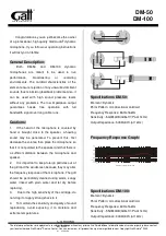
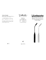
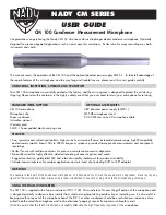
Figure 4 -
IEDA520DTB Desktop Base Installation
Alternative Single-Gang Electrical Box Installation
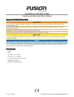
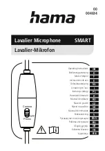
The IEDA524-H is shipped with a plastic back box that can be used if the installation does not allow for the recom-
mended 2-gang electrical box installation. This box can also be used if you later decide to mount the unit to a desktop
base. The box has two keyholes that fit a standard single-gang electrical box hole pattern. This allows you to install the
unit in an installation where you may already have single-gang boxes installed. The box provides a slight forward slant
which is excellent for surface mounting the unit in a console. Figure 5 illustrates the process for mounting the unit in such
an application. The washers shown are optional and can be used to prevent the unit from being forced off of the box due
to the keyhole mounting points.
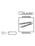
Figure 5 -
Alternate Single-Gang Electrical Box Method A
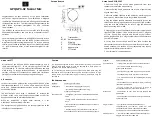
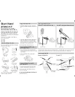
Figure 6 illustrates an alternative mounting option where the box has been rotated 180˚ to provide a slight backward
slant to the microphone station. In this case, you must use appropriately sized washers when attaching the box to the
electrical box to prevent it from sliding off due to the keyhole mounting points. When the plastic box is attached in this
orientation, you will no longer have direct access to the DIP switches or connectors. You will need to set the DIP switches
and make any connections prior to placing the unit in the box. Use care when routing the cables as the clearance
between the connector and the box is minimal.
Not Included