background image

User  Manual 

22 


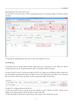
The above prompt will appear if there are no tags available for operation in the radio frequency area. 

For  the  meaning  of  other  returned  information,  users  can  refer  to  the  document: 

R2000  module  serial 

interface communication protocol V4.0. 

Every time the UID of the tag is successfully read, the buzzer will beep once. If the buzzer beeps slightly 

longer, it means that the reader has activated the anti-collision function and recognized multiple tags at the 

same time.


2.5 

Other Settings 

2.5.1Operating Temperature Monitoring 


When  the  reader  is  used  continuously  at  high  intensity,  heat  will  be  generated.  The  user  can  monitor  the  internal 

working  temperature  of  the  reader  through  the  built-in  temperature  sensor  to  avoid  overheating  (the  working 

temperature  exceeds  65  degrees  Celsius).  If  the  temperature  is  too  hot,  you  can  stop  reading  and  writing  tags  for  a 

period of time. 


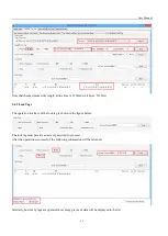
The operation interface for monitoring temperature is as follows: 


2.5.2 Set GPIO Level 


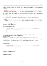
GPIO  is  the  general-purpose  input  and  output  interface.  It  provides  users  with  the  function  of  triggering  and 

controlling  each  other  between  peripheral  devices  and  readers.  This  reader  provides  two  optically  isolated  inputs 

(GPIO1 and GPIO2) and two relay outputs (GPIO3 and GPIO4). 


Summary of Contents for RF900I-8

Page 1: ...User Manual 1 RF900I 8 User Manual ...

Page 2: ...OR 9 2 2 4 MEASURE RF PORT RETURN LOSS 10 2 3 ISO 18000 6C TAG INVENTORY 10 2 3 1 REAL TIME MODE 10 2 3 2 USERS DEFINE SESSION ID INVENTORYING PARAMETER OF INVENTORIED FLAG 13 2 3 3 FAST SWITCHING ANTENNA TO INVENTORY TAGS 14 2 4 ACCESSING ISO 18000 6C TAG 15 2 4 1READ TAGS 16 2 4 2 WRITE TAGS 17 2 4 3 LOCK TAGS 19 2 4 4 KILL TAGS 20 2 4 5 TAG SELECTION 20 2 4 6 ERROR DISPLAY MIGHT BE RETURNED 21 ...

Page 3: ...User Manual 3 1 RF900I 8 View 1 1 Front View 1 2 Back View ...

Page 4: ...Connect the antenna s with the antenna port 2 1 3 Step 3 Connecting Data Line to Reader Method NO 1 You can connect the reader to your PC via RS 232 serial port Method NO 2 You can also connect the reader to your PC via TCP IP 2 1 4 Step 4 Operating Reader via Demo Put the UHFDemo exe reader dll customControl dll into the same folder and double click UHFDemo exe to run the software Open the softwa...

Page 5: ...click the Connect button if the serial port is not occupied the following information will be displayed in the Operation History below If the reader is connected via TCP IP you need to perform the following steps 1 Make sure there is an Ethernet card in the PC 2 Make sure that the settings of the PC and the reader are in the same network segment The reader as a server uses the following default se...

Page 6: ...re below in the connection mode Click the Connect button if the connection is successful the following information will be displayed in the Operation History blow Next we will test the communication with the reader Click the button at the position shown in the oval frame in the figure below Click the button to read the firmware version or click the button to read the reader identification the inte...

Page 7: ...r successfully connecting the reader with PC we need to set some of the most basic RF parameters such as RF output power and RF spectrum RF parameter setting is in the Reader Setup RF Setup page as shown in the figure below 2 2 1 Setting RF Output Power RF Output Power is the strength of RF output signal from antenna port whose unit is dBm ...

Page 8: ... shown in the following figure 2 2 2 Setting RF Spectrum In different regions there are different requirements for the RF Spectrum There are two ways to set the RF Spectrum of the reader Method 1 Use the default carrier frequency of the reader Please refer to Frequency parameter tablet in Communication protocol for more information about the carrier frequency Frequency range the reader supports 86...

Page 9: ... after the reader is powered off 2 2 3 Antenna Connection Detector The function of antenna connection detection is to check whether the antenna is connected to the port before reading and writing tags If there is no connection notify the user that the antenna is not connected Before use the user needs to turn on this function and view it through the interface shown in the figure below The interfac...

Page 10: ...ce the RF output power or adjust the antenna installation position The return loss of the antenna port and VSWR are two different expressions of the same concept The corresponding relationship is shown in the following table Return loss of antenna port dB Standing wave ratio VSWR of antenna port 40 1 02 26 1 11 20 1 22 18 1 29 15 1 43 10 1 92 2 3 ISO 18000 6C tag inventory After correctly connecti...

Page 11: ...y Real time mode page to switch the software interface to real time mode Manually tick the connected antenna Then set the number of cycles for each command The meaning of this parameter is the number of repeated executions of the inventory command For example if it is set to 1 each inventory command executes an anti collision algorithm Set to 2 then each inventory command will execute the anti col...

Page 12: ... ms Total Inventory Duration Total elapsed time since click on Inventory Tag unit ms ID The serial number of data EPC EPC number of tag PC Protocol Control word of tag Identification Count Times of tag identified RSSI The signal strength when tag was identified at the last time Carrier Frequency Carrier Frequency of tag which is identified at the last time It is convenient for users to analyze the...

Page 13: ...Inventoried Flag According to the user defined Session ID and Inventoried Flag parameters to inventory the reader can inventory according to the user defined session parameters four types of session S0 S1 S2 S3 and the inventoried flag two inventoried flags A B parameters ...

Page 14: ...is time the function of quickly switching the antenna of the inventory tag needs to be used Use cmd_name_fast_switch_ant_inventory command see R2000 module serial interface communication protocol V4 0 With this command users do not need to send antenna switching commands so it is faster and more efficient On one antenna the time consumed to read one or two tags is only about 50 milliseconds Please...

Page 15: ...orking time of the antenna Set the appropriate number of round according to the number of tags in front of the antenna The default number of round is 1 The sequence of antenna switching and whether to select the antenna inventory can be set as shown in the figure below 2 4 Accessing ISO 18000 6C Tag Click the Access Tag selection box to enter the access tag interface as shown below ...

Page 16: ...eet the tag specifications otherwise an error message will appear The specific read tag operation is shown in the figure below 1 Select the tag that needs to be operated read in the real time inventory interface and all the read tags will be displayed in the drop down list and click the Selected button on the right 2 Select the storage area that needs to operate the tag In the example select the E...

Page 17: ... password and writing data The password area is the part of the password password in the tag storage area Including kill password and access password Both the kill password and the access password are 4 bytes Among them the address of the inactivation password is 00H 03H in bytes the address of the access password is 04H 07H in bytes The specific tag writing operation is shown below 1 Select the t...

Page 18: ...nter the data to be written in the Data to be written HEX such as 112233445566778899AABBCC 12 bytes 6 Click the Write button to write the content that needs to be written into the corresponding storage area of the tag and display it in the data column of the list box How many tags are successfully operated how many pieces of data will be displayed in the list Unlike reading tags there is no conten...

Page 19: ...ck Tags The operation interface of the lock tag is shown in the figure below The lock tag must provide an access password to proceed After the operation is successful the following information will be returned Similarly how many tags are operated how many pieces of data will be displayed in the list ...

Page 20: ...essing tags how many tags are killed how many pieces of data are displayed in the list 2 4 5 Tag Selection In many cases we hope that no matter how many tags there are in the radio frequency area only one tag with a known EPC number can be accessed At this time the tag function EPC matching function of the selected operation needs to be used In the accompanying demo software taking the real time i...

Page 21: ...wn below 2 4 6 Error Display Might Be Returned Errors occur if wrong operations done Inventory success access failure There are two steps to get access to tags firstly tag inventory secondly access tags Picture above shows the inventory is successful but we can t access to tags Two reasons why 1 Parameters incorrect for example zones password EPC TID User to be read do not exist 2 Tags beyond the ...

Page 22: ...ure Monitoring When the reader is used continuously at high intensity heat will be generated The user can monitor the internal working temperature of the reader through the built in temperature sensor to avoid overheating the working temperature exceeds 65 degrees Celsius If the temperature is too hot you can stop reading and writing tags for a period of time The operation interface for monitoring...

Page 23: ...f multi tag recognition This function is more used to test tags or readers The operation interface is as follows It should be noted that the buzzer sound after successful power on self test is not controlled by this setting After the setting is completed the state of the buzzer will be kept in the FLASH inside the reader and will not be lost after power off 2 5 4 Changing The Serial Communication ...

Page 24: ...ent it is necessary to develop their own programs The accompanying document R2000 module serial interface communication protocol V4 0 doc provides a complete interface for operating the reader This interface is based on serial communication so no matter the user s physical interface is RS232 or TCP IP the reader will follow the definition of this interface The demonstration program provides an imp...

Page 25: ...ly sending data can be used by users to debug serial commands and it has the function of automatically calculating the checksum In addition the attached document also includes the complete source code of this demo program based on the C language development of the Net platform for user reference so that applications based on this reader can be developed at the fastest speed ...

Page 26: ...and if not installed and used in accordance with the instructions may cause harmful interference to radio communications However there is no guarantee that interference will not occur in a particular installation If this equipment does cause harmful interferenceto radio or television reception which can be determined by turning the equipment off and on the user is encouraged to try to correct the ...

Reviews: