


INSTALLATION OF THE PRODUCT
p.19
• After fixing the LX006/SR on the wall mount, you can’t initialize the system by t
his procedure. But you can initialize it through Application Software
• If you initialize the system using software, all data except for the IP setting retur
ns to the default.
• If you initialize the hardware system, all data settings return to the factory defau
lt. (including IDs, fingerprint data, master ID, card number output format, IP)
• If the communication address is set to 255, the initialization process gets started
immediately
4
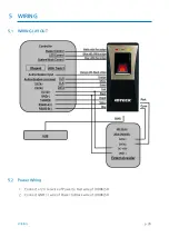
COMMUNICATION ID SETTING
LX006/SR can upload/ download user’s information by application software and adjust setti
ng values. Communication ID is the unique communication address to recognize each LX00
6/SR in the software so each communication ID on the same communication loop must not
be duplicated.
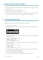
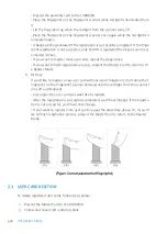
There is 8-bit DIP switch on the back of LX006/SR for communication ID setting and each ch
annel of DIP switch has assigned address values. The communication ID is calculated by the s
um value of each bit set to “ON” position. Communication ID can be set from ‘0’ to ‘255’. Ref
er to examples below to set communication ID.
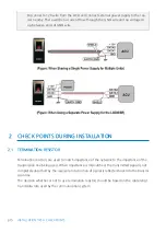
Each communication ID in the same communication loop must not be duplicated. I
f the same communication IDs are on the loop, it may cause communication error.
Summary of Contents for LX006
Page 1: ......
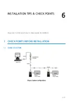
Page 15: ...PRODUCT EXPLANATION 5 p 10 1 PANEL LAYOUT...
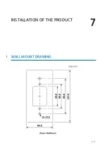
Page 22: ...INSTALLATION OF THE PRODUCT 7 p 17 1 WALL MOUNT DRAWING...
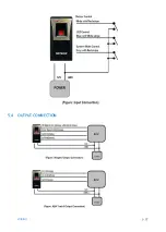
Page 27: ...p 22 WIRING 5 4 OUTPUT CONNECTION...
Page 33: ...p 28 TCP IP COMMUNICATION PORT CONNECTION...
Page 45: ...p 40 OUTPUT MODE 3 1 NORMAL OUTPUT MODE 3 2 EXTENSION OUTPUT MODE SET BY APPLICATION SOFTWARE...
Page 49: ...p 44 How to register fingerprint 2 How to register fingerprint...


