


p.18
SYSTEM INITIALIZATION
2
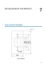
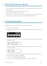
INSTALLATION OF WALL MOUNT
●
Place the Wall Mount on the desired position on the wall and mark the locations of the
2 screw holes.
●
Drill a hole in the center of the Wall Mount for cable.
●
Take out the cable from the center of hole.
●
Wire cable to four connecters and then perform initialization and set communication ID.
●
By using of one screw on the bottom, fix the Wall Mount with LX006/SR.
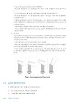
3
SYSTEM INITIALIZATION
Initialize the system using the DIP switch on the rear of the product.
1.
Disconnect the power supply.
2.
Position the DIP switch on the rear of the product to ON (upside) and apply power to th
e product.
3.
The product sounds a beep once with a voice message, and proceed with the hardware
initialization process.
4.
When the initialization is done, the product sounds a beep three times with a completi
on message output.
The product keeps sounding the beep until you change the communication address.
5.
Use the DIP switch to specify the BOARD ID.
Refer to “7.4 COMMUNICATION ID SETTING”.
6.
You must specify the communication address and register the master ID.
Summary of Contents for LX006
Page 1: ......
Page 15: ...PRODUCT EXPLANATION 5 p 10 1 PANEL LAYOUT...
Page 22: ...INSTALLATION OF THE PRODUCT 7 p 17 1 WALL MOUNT DRAWING...
Page 27: ...p 22 WIRING 5 4 OUTPUT CONNECTION...
Page 33: ...p 28 TCP IP COMMUNICATION PORT CONNECTION...
Page 45: ...p 40 OUTPUT MODE 3 1 NORMAL OUTPUT MODE 3 2 EXTENSION OUTPUT MODE SET BY APPLICATION SOFTWARE...
Page 49: ...p 44 How to register fingerprint 2 How to register fingerprint...


