


Part 1 – Introduction
11
•
Alarm In 1 through 4
This DVR is capable of responding to event signals
from external alarm in devices. Connect mechanical
or electrical switches to AI 1 through 4 and the GND
(ground) connector. In order to be recognized by the
DVR, the signal from an alarm in device must be more
than 3.0V (Normally Closed) or less than 0.3V (Normally
Open) and maintained for at least 0.5 seconds. The alarm
in voltage range is 0V to 5V. For more information on
alarm in setup, refer to the
Alarm-In in the operation
manual
.
•
GND (Ground)
Connect alarm in or out's ground cable to the GND
connector.
All connectors marked "GND" are common connectors.
•
NC/NO (Relay Alarm Outputs)
This DVR is capable of activating/deactivating buzzers,
lights, and other external devices. Connect the device to
the C and NO (Normally Open) connectors. NC/NO is a
relay output which sinks 1A@125VAC and 1A@30VDC. For
more information on alarm out setup, refer to the
Alarm-
Out in the operation manual
.
•
Connector Arrangement
AI1 through AI4
Alarm In 1 through 4
GND
Ground
NO
Normally Open Relay Alarm
Out
C
Relay Common
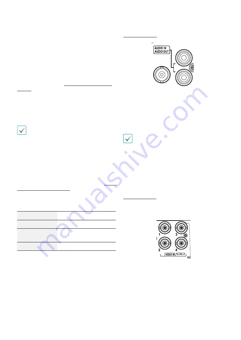
Audio Connection
Connect the audio device to the
AUDIO IN
port and
speakers with a built-in amplifier to the
AUDIO OUT
port.
Use the
AUDIO OUT
port to listen to audio from analog
cameras.
Use the
AUDIO IN
port to establish two-way
communication with cameras.
• This DVR does not feature a built-in audio amplifier
unit and therefore requires the user to purchase a
speaker system with a built-in amplifier separately.
It's possible to connect an amplified audio source to
the DVR, but microphones that do not have a built-
in amplifier will not function properly if connected
to the DVR directly. If this is the case, connect the
microphone to the DVR via a pre-amp.
• Check your local laws and regulations on making
audio recordings.
Video Connection
•
Video In Port
Connect the coaxial cables from the video sources to the
composite Video In connectors or BNC connectors.