background image

Part 1 - Menu Setup

10


WDR: 

When objects are not identified and seen dark, 

WDR

 allows you to see the screen vivid and clear.

LENS

 function does not work while the 

WDR

 mode is 

being activated.


-

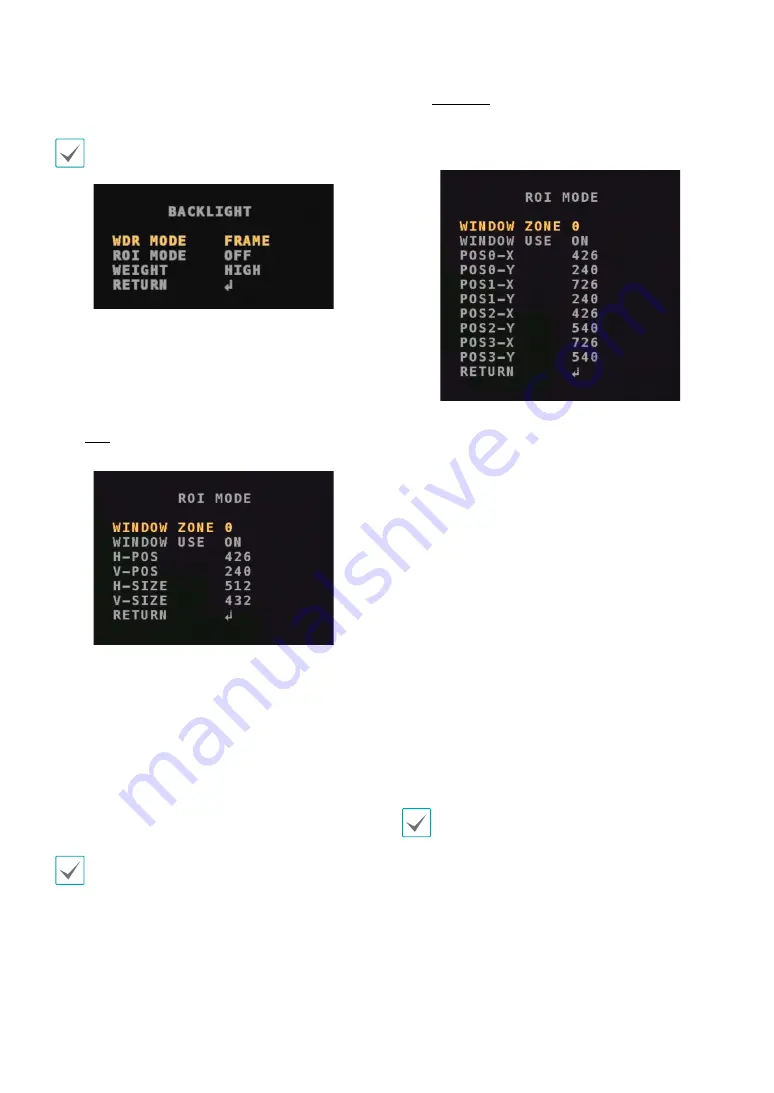
WDR MODE: 

Select the mode of WDR. (FRAME/

LINE)


-

ROI MODE: 

Lower the brightness of the selected 

area in order to see objects clearly. The area can be 
adjusted in the shape of 

BOX

 or 

POLYGON

.

BOX

Select the applying area in the shape of box.


-

WINDOW ZONE: 

Select the box. (0~3)


-

WINDOW USE: 

Choose the state of the box. (

ON

OFF)


-

H-POS: 

Adjust the horizontal start position. 

(0~2608)


-

V-POS: 

Adjust the vertical start position. (0~1960)


-

H-SIZE: 

Adjust the horizontal size of the area. 

(0~2608)


-

V-SIZE: 

Adjust the vertical size of the area. (0~1960)

The maximum of the adjustable values may vary 
depending on the resolution.

POLYGON

Select the applying area in the shape of polygon. 
The four vertexes can be moved in order to adjust 
a range. 


-

WINDOW ZONE: 

Select the polygon. (0~3)


-

WINDOW USE: 

Choose the state of the polygon. 

(

ON

OFF)


-

POS0-X: 

Adjust the vertex of the X-coordinate at 

the top left. (0~2603)


-

POS0-Y: 

Adjust the vertex of the Y-coordinate at the 

top left.  (0~1955)


-

POS1-X: 

Adjust the vertex of the X-coordinate at 

the top right. (5~2603)


-

POS1-Y: 

Adjust the vertex of the Y-coordinate at the 

top right. (0~1955)


-

POS2-X: 

Adjust the vertex of the X-coordinate at 

the bottom left. (0~2603)


-

POS2-Y: 

Adjust the vertex of the Y-coordinate at the 

bottom left. (5~1960)


-

POS3-X: 

Adjust the vertex of the X-coordinate at 

the bottom right. (5~2608)


-

POS3-Y: 

Adjust the vertex of the Y-coordinate at the 

bottom right. (5~1960)

The maximum of the adjustable values may vary 
depending on the resolution.


-

WEIGHT: 

Select the weight level. Increasing 

the level makes the screen dark by reducing 
overexposure to light. (LOW/MIDDLE/HIGH)

Summary of Contents for TC-D5531RX

Page 1: ...DirectCX Camera Operation Manual TC D5531RX TC D5531RXP TC D5531WRX TC D5531WRXP TC D5532RX TC D5532WRX...

Page 2: ...explanation about some functions may not be incorporated The manufacturer is not responsible for any problems resulting from the use thereof The information contained herein is subject to change with...

Page 3: ...ng storm or when it is left unattended and unused for long periods of time unplug it from the wall outlet and disconnect the antenna or cable system This will prevent damage to the equipment due to li...

Page 4: ...d other European countries with separate collection systems This marking shown on the product or its literature indicates that it should not be disposed with other household wastes at the end of its w...

Page 5: ...1 Part 1 Menu Setup 6 Lens 6 Motorized 7 Exposure Compensation 7 White Balance 8 Backlight Compensation 9 Day Night Function 11 Dynamic Noise Reduction 12 Image Compensation 12 Motion Detection 15 Sys...

Page 6: ...dicates that there are submenus Press OSD button to display submenus 4 Move the yellow indicator to the SAVE EXITand press the OSD button to exit Dark gray functions are not available depending on the...

Page 7: ...mpensation 1 From the MENUscreen move the yellow indicator to the EXPOSURE using the UP or DOWN button 2 Press the OSD button to load the submenus of the EXPOSURE BRIGHTNESS Adjust the brightness on t...

Page 8: ...t of the camera and press the OSD button during three seconds then a message PUSHING appears and the setting will be applied If the surrondings change AWC SET should be re adjusted MANUAL From the C T...

Page 9: ...st the range of overexposure to light COLOR Select a color applied to the area of the overexposure BLK WHT YEL CYN GRN MAG RED BLU BLC When a subject is against strong light BLC allows you to see the...

Page 10: ...ution POLYGON Select the applying area in the shape of polygon The four vertexes can be moved in order to adjust a range WINDOW ZONE Select the polygon 0 3 WINDOW USE Choose the state of the polygon O...

Page 11: ...IR Adjust the level to prevent overexposure to infrared light 0 20 D N THRES Set up the standard value during the time when day turns into night 0 20 N D THRES Set up the standard value during the tim...

Page 12: ...n OFF LOW MIDDLE HIGH Image Compensation The IMAGE function allows you to optimize the image quality by adjusting various options 1 From the MENUscreen move the yellow indicator to the IMAGE using the...

Page 13: ...osition 0 61 H SIZE Adjust the horizontal size of the zone 0 81 V SIZE Adjust the vertical size of the zone 0 61 Y LEVEL Adjust the brightness of the zone 0 20 CB LEVEL Adjust the blue color range of...

Page 14: ...Detection The MOTION function enables the camera to detect moving objects 1 From the MENUscreen move the yellow indicator to the MOTION using the UP or DOWN button 2 Press the L or R button to select...

Page 15: ...0 60 The maximum of the adjustable values may vary depending on the resolution SENSITIVITY Increasing the sensitivity level makes the motion detection more sensitive but the resolution may be reduced...

Page 16: ...ect USER you can randomly designate the value at OFFSET The higher the value the brighter the screen and also the more blurred the impression of colors 0 32 COLOR SPACE Select the impression of a colo...

Page 17: ...Part 1 Menu Setup 17 Save Exit Press SAVE EXIT button to save the settings and exit V1 2...

Page 18: ...IDIS Co Ltd For more information please visit at www idisglobal com...

Reviews: