


Part 1 – Introduction
14
Rear Panel Connections
Video Connection
●
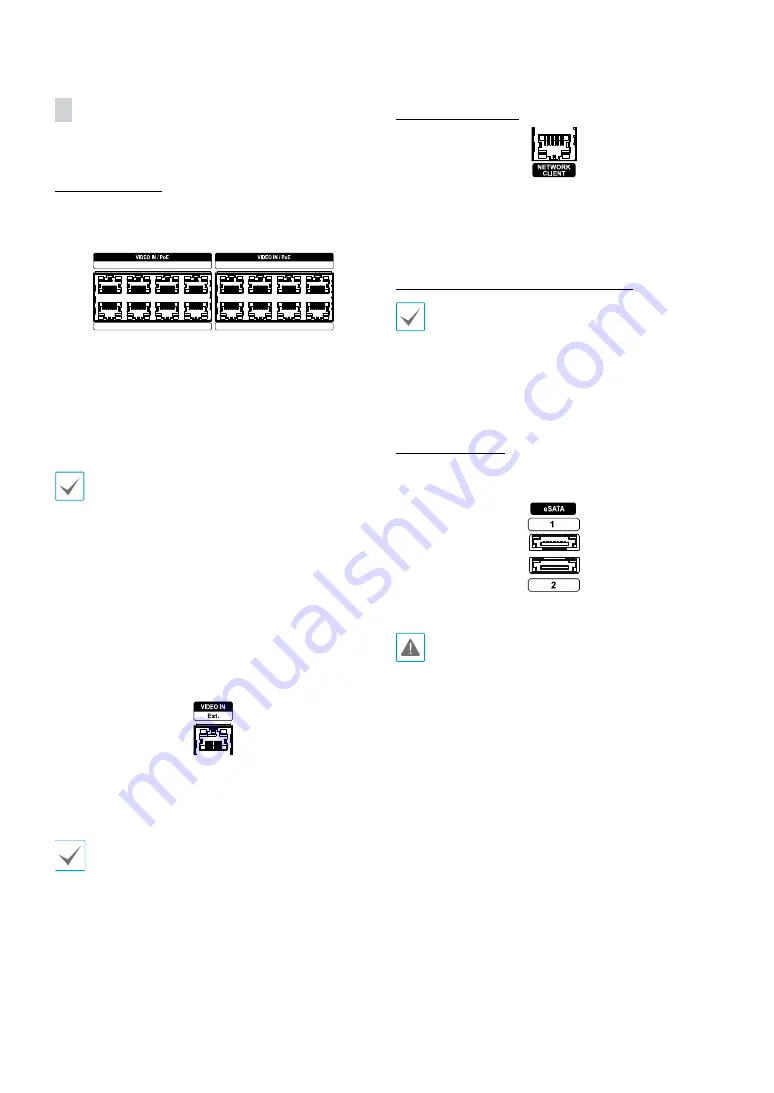
Video In/PoE Port
1
3
5
7
2
4
6
8
9
11
13
15
10
12
14
16
Connect network cameras or video encoders to the
NVR using RJ-45 cable (Cat5e, or Cat6). In addition to
cameras or video encoders, you can connect external
hubs (Optional: DH-2112PF, DH-2128PF) to form a
network. The NVR recognizes DirectIP™ network cameras
automatically. Ports 1 through 16 support PoE.
•
We recommend that you use the Ext. port for
connecting to an external hub and using features
such as camera alignment.
•
Green LED on the right will turn on when PoE comes
on line. Orange LED on the left will then flash once a
link has been established.
•
If more than 16 cameras from video encoders are
registered on the NVR, video may not be displayed
smoothly in a remote program.
●
Video In / Ext. Port
This port does not support PoE. It's possible to establish a
network with network cameras and external hubs using
a Cat6 cable.
•
Green LED on the right will turn on if connected to
a 1000 BASE-T network. Orange LED on the left will
then flash once a link has been established.
•
When using a Cat5e cable, the data transfer speed
may decrease depending on how to establish a
network.
Network Connection
This NVR is capable of connecting to networks via an
ethernet connector. Connect an RJ-45 cable (Cat5e, or
Cat6) to the NVR's network port. It's possible to operate
and upgrade the NVR remotely over a network. Fore
more information on ethernet connection setup, refer to
Network Setup in the operation manual
.
•
Connector directions may vary depending on the
NVR model.
•
Green LED on the right will begin to flash if
connected a 1000 BASE-T network. Orange LED
on the left will then flash once a link has been
established.
eSATA Connection
Connect external hard drives to these ports.
1
3
5
7
9
11
13
15
10
12
14
16
2
8
6
4
!
@
#
1
2
3
4
5
6
0
7
8
9
Do not connect or disconnect an eSATA device while
the NVR is powered on. To connect an eSATA device,
first turn off the NVR and unplug the power cable.
Connect the eSATA device and then power the eSATA
device first and then NVR back on. To disconnect an
eSATA device, first turn off the NVR and unplug the
power cable. Turn off the eSATA device and then
disconnect the eSATA connection cable.


