


Part 1 – Introduction
10
Overview
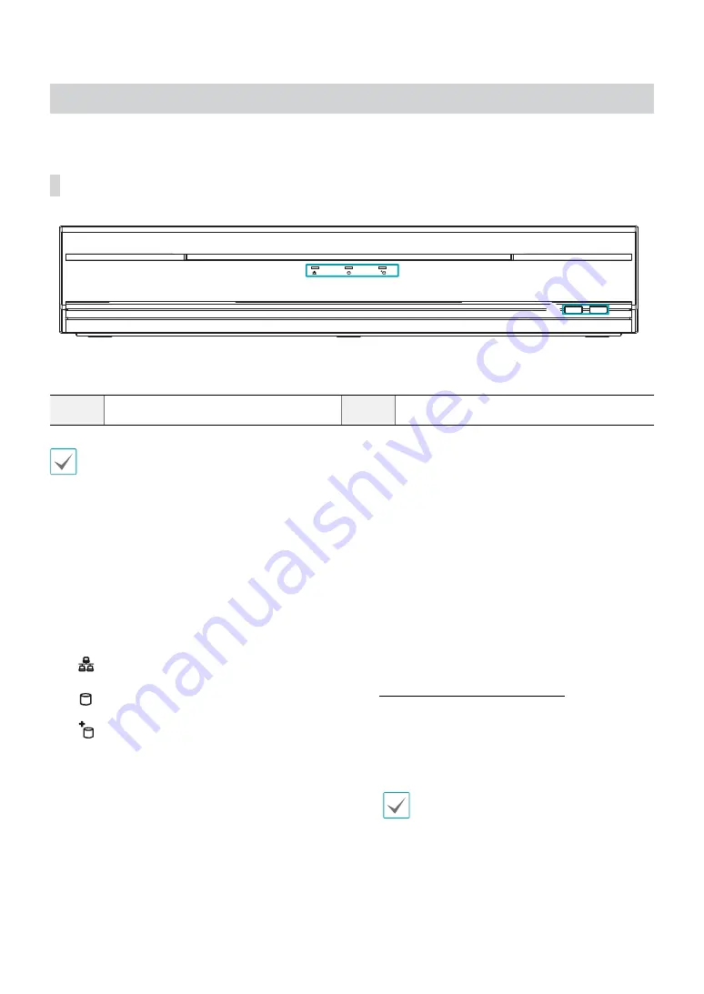
Front Panel
1
2
1
LEDs
2
USB Ports
•
Remote control sensor is located on the bottom center of the front panel. Ensure that the sensor remains unobstructed at
all times. If obstructed, the sensor might not be able to receive remote control signals.
•
Placing a Wi-Fi, Bluetooth, or any other wireless communication device near the NVR may interfere with remote control
signal transmission.
•
Access various windows and menus using a USB mouse as you would on a personal computer.
•
For easier system configuration, a USB mouse is recommended.
1
LEDs
●
Power LED
: Lights up while the main unit is in
operation.
●
Network LED
: Flashes when the main unit is
linked to an ethernet.
●
HDD LED
: Flashes when data is being written on
the HDD or a video search is in progress.
●
eSATA LED
: Lights up when the main unit is
connected to an eSATA device.
2
USB Ports
●
Storage Device Connection
Connect an external USB hard drive or a USB flash
memory device to one of the USB ports for use with
the Clip Copy feature. The external storage device
should be placed as close to the NVR as possible.
It is recommended that you use a connection cable
that is no longer than 180cm in length. Use the
connection cable included with your external storage
device to connect the device to one of NVR's USB
ports. For more information Clip Copy, refer to the
Clip Copy in the operation manual
.
●
Peripheral Device Connection
Use the USB ports to connect peripherals such as a
USB mouse to the NVR. You can also use a USB-to-
serial converter and connect multiple text-in devices
to the NVR at the same time.
For USB flash memory devices, the NVR supports
the FAT32 file format only.


