


Part 1 – Introduction
16
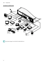
Network Connection
AUDIO IN
AUDIO OUT
VGA OUT
HDMI
eSATA
NETWORK
CLIENT
VIDEO IN / PoE
NC C NO AR I G
RS -485
- +
A/1 A/2 A/3 A/4 G
Tx Rx
RS -232
CAUTION : TO REDUCE THE RISK OF ELECTRIC SHOCK.
DO NOT REMOVE COVER (OR BACK).
NO USER-SERVICEABLE PARTS INSIDE.
REFER SERVICING TO QUALIFIED
SERVICE PERSONNEL.
1
3
2
4
CAUTION
RISK OF ELECTRIC SHOCK
DO NOT OPEN
A
C
E
G
VIDEO IN
Ext.
B
D
F
H
100-240V~
This NVR is capable of connecting to networks via an
ethernet connector. Connect an RJ-45 cable (Cat5,
Cat5e, or Cat6) to the NVR's network port. It's possible to
operate and upgrade the NVR remotely over a network.
Fore more information on ethernet connection setup,
refer to
Network Setup in the operation manual
.
•
Connector directions may vary depending on the
NVR model.
•
Green LED on the right will begin to flash if
connected a 1000 BASE-T network. Orange LED
on the left will then flash once a link has been
established.
eSATA Connection
Connect external hard drives to these ports.
AUDIO IN
AUDIO OUT
VGA OUT
HDMI
eSATA
NETWORK
VIDEO IN
NC C NO AR I G
RS -485
- +
A/1 A/2 A/3 A/4 G
Tx Rx
RS -232
CAUTION : TO REDUCE THE RISK OF ELECTRIC SHOCK.
DO NOT REMOVE COVER (OR BACK).
NO USER-SERVICEABLE PARTS INSIDE.
REFER SERVICING TO QUALIFIED
SERVICE PERSONNEL.
1
3
2
4
CAUTION
RISK OF ELECTRIC SHOCK
DO NOT OPEN
A
C
E
G
B
D
F
H
100-240V~
DR-4100P and DR-4200P Series features 2 eSATA ports.
Do not connect or disconnect an eSATA device while
the NVR is powered on. To connect an eSATA device,
first turn off the NVR and unplug the power cable.
Connect the eSATA device and then power the eSATA
device first and then NVR back on. To disconnect an
eSATA device, first turn off the NVR and unplug the
power cable. Turn off the eSATA device and then
disconnect the eSATA connection cable.
RS-232 Connection
Connect an external device such as a POS unit to this
port.
AUDIO IN
AUDIO OUT
VGA OUT
HDMI
eSATA
NETWORK
VIDEO IN
NC C NO AR I G
RS -485
- +
A/1 A/2 A/3 A/4 G
Tx Rx
RS -232
CAUTION : TO REDUCE THE RISK OF ELECTRIC SHOCK.
DO NOT REMOVE COVER (OR BACK).
NO USER-SERVICEABLE PARTS INSIDE.
REFER SERVICING TO QUALIFIED
SERVICE PERSONNEL.
1
3
2
4
CAUTION
RISK OF ELECTRIC SHOCK
DO NOT OPEN
A
C
E
G
B
D
F
H
100-240V~
RS-485 Connection
This NVR supports the RS-485 half-duplex serial
communication protocol for connecting to external
devices such as POS units.
AUDIO IN
AUDIO OUT
VGA OUT
HDMI
eSATA
NETWORK
VIDEO IN
NC C NO AR I G
RS -485
- +
A/1 A/2 A/3 A/4 G
Tx Rx
RS -232
CAUTION : TO REDUCE THE RISK OF ELECTRIC SHOCK.
DO NOT REMOVE COVER (OR BACK).
NO USER-SERVICEABLE PARTS INSIDE.
REFER SERVICING TO QUALIFIED
SERVICE PERSONNEL.
1
3
2
4
CAUTION
RISK OF ELECTRIC SHOCK
DO NOT OPEN
A
C
E
G
B
D
F
H
100-240V~
Alarm Connection
Connect alarm connectors to these ports.
AUDIO IN
AUDIO OUT
VGA OUT
HDMI
eSATA
NETWORK
VIDEO IN
NC C NO AR I G
RS -485
- +
A/1 A/2 A/3 A/4 G
Tx Rx
RS -232
CAUTION : TO REDUCE THE RISK OF ELECTRIC SHOCK.
DO NOT REMOVE COVER (OR BACK).
NO USER-SERVICEABLE PARTS INSIDE.
REFER SERVICING TO QUALIFIED
SERVICE PERSONNEL.
1
3
2
4
CAUTION
RISK OF ELECTRIC SHOCK
DO NOT OPEN
A
C
E
G
B
D
F
H
100-240V~
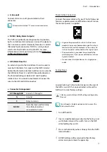
Press down on the button and insert the cable into
the opening. Release the button and then pull on the
cable slightly to ensure it is held securely in place. To
disconnect the cable, press down on the button again
and pull the cable out.
●
Alarm In 1 through 4
This NVR is capable of responding to event signals
from external alarm in devices. Connect mechanical or
electrical switches to AI 1 through 4 and the G (ground)
connector. In order to be recognized by the NVR,
the signal from an alarm in device must be less than
0.3V (Normally Open) and maintained for at least 0.5
seconds. The alarm in voltage range is 0V to 5V. For more
information on alarm in setup, refer to the
Alarm-In in
the operation manual
.