


Part 1 – Introduction
11
1
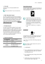
Panic Recording
Button
Pressing
Panic Recording
1
2
3
4
5
6
7
8
9
0
button displays the
icon and commences recording irrespective of the
current schedule.
Press the button again to deactivate Panic Recording
mode.
2
Alarm
Button
Pressing the
Alarm
1
2
3
4
5
6
7
8
9
0
button while the alarm has
been activated resets all NVR outputs, including the
built-in buzzer. Pressing the button while the alarm is
off displays the event log on the screen.
3
PTZ
Button
Pressing the
PTZ
1
2
3
4
5
6
7
8
9
0
button initiates PTZ mode,
allowing you to control PTZ cameras.
In PTZ mode, use the arrow buttons to move the
camera up, down, left, and right.
1
2
3
4
5
6
Zoom-In
1
2
3
4
5
6
Zoom-Out
1
2
3
4
5
6
Focus Near
1
2
3
4
5
6
Focus Far
1
2
3
4
5
6
Load preset window
1
2
3
4
5
6
Save current position as a preset
4
Layout
Button
Press the
Layout
1
2
3
4
5
6
7
8
9
0
button to cycle through split
screen formats.
1x1> 2x2 > 1+5 > 1+7 > 3x3 > 4x4 > 5x5 > 6x6
5
Search Mode
Button
Pressing the
Search Mode
1
2
3
4
5
6
7
8
9
0
button initiates
Search mode, which will allow you to search for and
play back video recordings.
Pressing the
Search Mode
1
2
3
4
5
6
7
8
9
0
button while in
Search mode returns the screen to Live mode.
6
Menu
Button
Pressing the
Menu
1
2
3
4
5
6
7
8
9
0
button while in Live mode
displays the Live menu.
Pressing the
Menu
1
2
3
4
5
6
7
8
9
0
button while in Search
mode displays the Search menu on the top of the
screen.
Press the button once more to close the menu.
Pressing the
Menu
1
2
3
4
5
6
7
8
9
0
button while a camera
screen is selected by pressing
Enter (
$
)
button
in Live mode displays the Camera menu. Selecting
Camera Registration
displays NVR and IP Camera
Setup window.
Pressing the
Menu
1
2
3
4
5
6
7
8
9
0
button in Search mode
displays the
Control Area
menu. Selecting
Top
by
using this button in the
Control Area
menu displays
the Search menu. For more information on the
Control Area menu, refer to
Time-Lapse Search in
the operation manual
. Press the button once more
to close the menu.
Pressing and holding the
Menu
1
2
3
4
5
6
7
8
9
0
button for
3 seconds while in Playback mode activates One-
Touch mode and displays the clip copy window. If the
Search menu is displayed on the top of the screen,
One-Touch mode is not activated.
7
Camera
Button
Pressing the
Camera
button while in Live or Playback
mode displays images from the selected camera in
full screen. To select a camera whose channel is made
up of two digits, enter the digits in sequence using
the number keys.