background image

Part 4 - IDIS Web

98

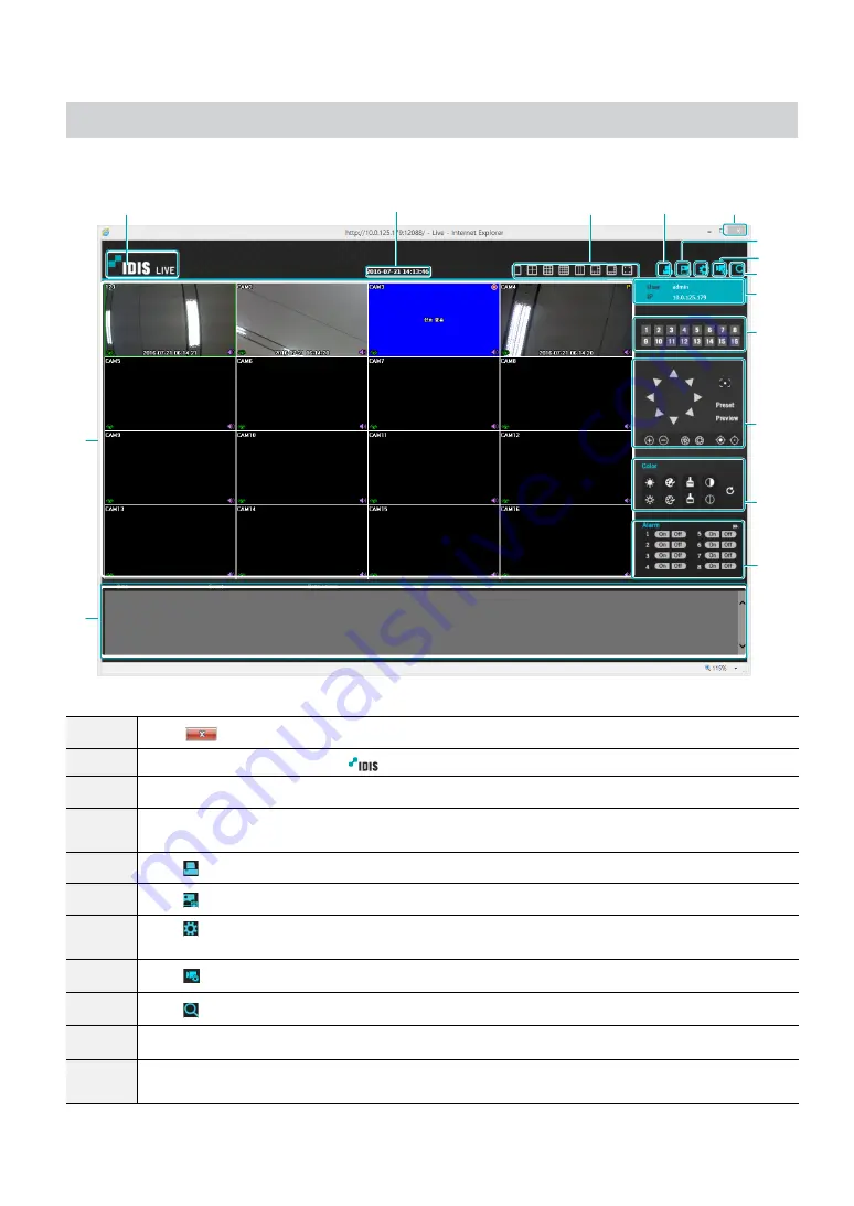
Web Live Mode

A remote web monitoring program that allows you to monitor images from remote locales in real-time.

0

!

@

#

$

7
8
9

1

3

4

2

^

%

5

1

Press 

 to terminate IDIS Web.

2

Place the mouse pointer on the 

 logo to check IDIS Web's version.

3

Displays the current time.

4

Select the desired mode. Changing the mode places the selected camera in the first cell of the layout 
that will be changed.

5

Click   to print the current video screen using a printer connected to the computer.

6

Click   to save the current video screen as an image file.

7

Click 

TYPE 1

 to configure rendering mode and OSD settings. Select rendering mode to adjust the video 

output rate or select which OSD elements to display on the screen from the OSD list. 

8

Click   to configure event, camera, stream settings, etc of NVR at remote locales.

9

Click   to switch over to Web Search mode.

0

Shows login information.

!

Select the camera you wish to monitor. Use the arrow buttons to navigate to the previous/next camera 
group.

Summary of Contents for DR-2304P

Page 1: ...Powered by Network Video Recorder Operation Manual DR 2304P DR 2308P DR 2316P ...

Page 2: ... and use If you need to disassemble the product for functionality expansion or repair purposes you must contact your retailer and seek professional assistance Both retailers and users should be aware that this product has been certified as being electromagnetically compatible for commercial use If you have sold or purchased this product unintentionally please replace with a consumer version Safety...

Page 3: ...ing instructions adjust only those controls that are covered by the operating instructions as an improper adjustment of other controls may result in damage and will often require extensive work by a qualified technician to restore the equipment to its normal operation E If the equipment has been dropped or the cabinet damaged F When the equipment exhibits a distinct change in performance this indi...

Page 4: ...E INTERFERENCE AT THEIR OWN EXPENSE WARNING CHANGES OR MODIFICATIONS NOT EXPRESSLY APPROVED BY THE PARTY RESPONSIBLE FOR COMPLIANCE COULD VOID THE USER S AUTHORITY TO OPERATE THE EQUIPMENT THIS CLASS OF DIGITAL APPARATUS MEETS ALL REQUIREMENTS OF THE CANADIAN INTERFERENCE CAUSING EQUIPMENT REGULATIONS WEEE Waste Electrical Electronic Equipment Correct Disposal of This Product Applicable in the Eur...

Page 5: ...d We are not responsible for any problems resulting from the use thereof The information contained herein is subject to change without notice Revisions or new editions to this publication may be issued to incorporate such changes The software included in this product contains some Open Sources You may obtain the complete corresponding source code depending on whether or not the source is publicly ...

Page 6: ...20 Camera Registration Mode 21 Login 21 Live Menu 23 Zoom 25 PTZ Control 25 Dewarping Control NVR 27 Dewarping Control Camera 27 Event Monitoring 27 Covert Camera 28 Context Menu Access 28 Edit Group 29 Video Recording 29 Panic Recording 29 Audio Recording 30 Video Recording Playback 30 All Channel Playback 30 Remote Control Buttons during Playback 30 Context Menu 30 Part 2 Configuration 31 Menu U...

Page 7: ...eral 43 Advanced Setup 43 Stream 50 Audio 51 SD Card 51 Upgrade 52 Record Setup 52 General 52 Schedule 53 Pre Event 55 Smart Failover 55 Event Setup 56 Video Analytics 56 Alarm In 60 Video Loss 60 Audio Detection 61 Recording Fail 62 Text In 62 ANPR 63 Camera System 64 Face Detection 64 Queue Management 65 VA Loss 66 Device Setup 66 Alarm Out 66 Remote Control 67 ...

Page 8: ...X_Upgrade 70 Network Setup 71 General 71 WAN 73 FEN 74 NetFS 75 RTSP 76 Firewall 76 NAT 77 Notification Setup 77 Schedule 77 Callback 78 Mail 78 Push 79 FTP 80 Display Setup 81 OSD 81 Main Monitor 81 Status Setup 82 Camera 82 Device 82 VA Box 82 System 83 Storage 83 Network 84 ...

Page 9: ...og Search 94 Thumbnail Search 95 Overlapped Recording Search 95 Part 4 IDIS Web 96 Web Live Mode 98 Web Search Mode 100 Part 5 Appendix 103 NAT Function Example 103 Camera WebSetup Connection 104 IDIS Web Connection through IDIS Camera 104 IDIS Center Program Connection through IDIS Camera 105 RTSP Connection through IDIS Camera 106 Memo 107 ...

Page 10: ...d Click the question mark button on the bottom left corner and refer to the instruction on setting up a password An email address and UPR files are required to find the password Otherwise you may not be able to find your password when you enter the incorrect information Setup Wizard Setup Wizard lets you configure basic settings required for operating the system Setup Wizard only appears during in...

Page 11: ... settings refer to the Date Time section under System Setup on page 32 3 Choose the desired Recording Method and click Next 4 Choose the desired Recording Quality and click Next Higher recording quality uses up more disk space Recording resolution is determined based on the selected recording quality High Video Quality Priority Profile Very high Standard Recording Profile High Longer Recording Tim...

Page 12: ...ord High Continuous Very high Motion Standard Continuous High Motion Low Continuous Standard Motion Continuous Very high High Low 5 Choose the desired codec and click Next 6 Click Finish to exit Quick Wizard Network Wizard After exiting from Quick Wizard the network with Network Wizard will start automatically 1 Select Network Wizard 2 Specify whether the system is connected to the Internet and cl...

Page 13: ...he router s UPnP function refer to the router s operation manual 4 Enter in the Device Name field the NVR name to be registered on the FEN server and then click Check to check its availability The device name you register on the FEN server will be a unique name used to identify the NVR Once registered the name can be used to access the NVR directly from clients such as the IDIS Center Check the na...

Page 14: ... mouse and select Camera Registration to run the Camera Registration mode It allows you to scan for the cameras connected to the NVR 1 2 3 4 5 1 Camera Scan Button 2 Camera View Menus 3 Camera List Area 4 Video Display Area 5 Apply Cancel Buttons You can also register cameras on the remote program For more information on the remote camera registration refer to Registration on page 13 ...

Page 15: ...optimize the performance Mode Select the scan mode Auto Scan LAN Lists cameras in a LAN environment If Auto Scan LAN fails to recognize a camera try using IP Address Scan instead IP Address Scan Enter the IP address of a camera The NVR scans for the camera matching the specified address If you enter IP address s range the NVR scans for cameras falling under the specified address s range By specify...

Page 16: ...tes an IP address automatically in the range of 10 10 0 128 to 10 10 254 254 by using DHCP to the camera connected to the NVR s VIDEO IN port On DHCP Server Video In Network is connected between NVR and network cameras only so Gateway does not have any meaning Subnet Mask is 255 255 0 0 Class B When several NVRs exist in the same network only one of NVRs has to be run as a DHCP server If several D...

Page 17: ...sily Export Button Exports the list of camera information on USB as a csv file Import Button Imports a camera information file csv file The user can edit a csv file directly A column indicates camera number B column the camera MAC address C column the Video In port of the video encoder in the csv file C column indicates only for video encoders If camera information displays as follows 5 00 11 22 1...

Page 18: ...gs please refer to the network camera manual Camera List Area 1 2 3 4 Registered Initial registration other NVRs Registration X 1 Screen Position Registration Status Identifies the camera s position in the video display area A blue background indicates a camera that is available for registration A gray background indicates an already registered camera Other registered cameras are shown in black ba...

Page 19: ...ge if the camera has not been registered to the NVR Information is not indicated on the bottom of the screen for cameras already registered to the NVR and the Screen Position Registration Info icon is shown with a black background Screen Position Registration Info icon for cameras registered to another NVR is shown with a steady orange background on top of a gray screen Camera Menu Right click on ...

Page 20: ...n mode without applying the changes It is not possible to register a camera that has already been registered to a different NVR Diagnosis Process When the camera is registered to the NVR Self diagnosis runs automatically for the new registered and changed cameras If Self diagnosis is processing Diagnosis Processing message will be displayed If Self diagnosis is failed Diagnosis Requirement message...

Page 21: ...ult password for the admin account Select admin and then OK without entering a password to log in Leaving the admin account unassigned with a password poses a security risk Please assign a password at your earliest convenience A warning message will continue to be displayed until a password is assigned Click on the button next to the password field using the mouse This will bring up a virtual keyb...

Page 22: ...ting SSL TLS For more information on e mail refer to Mail on page 78 and SMTP Setup on page 79 3 Enter an UPR User Password Reset verification and then click on UPR Verification button 4 Select the UPR file and then click on Import button To use UPR function the UPR file must be saved in advance For more information on saving the UPR file refer to User on page 35 You can reset the password using a...

Page 23: ...logged out state the login icon is shown 2 Layout Used to change the screen layout to single screen 1x2 corridor format 1x3 2x2 1 5 1 7 3x3 1 12 or 4x4 Corridor Format Divides the screen into 3 panes This format displays vertically and is set to display the optimized video of the camera when using the camera s pivot feature This is particularly effective when monitoring hallways passages and other...

Page 24: ...equence in 2x2 split screen mode 1 1 1 1 1 1 3 3 3 3 3 3 2 2 2 2 2 2 4 5 6 15 16 4 If using the Full Sequence setting page numbers appear on the system status area on the upper right part of the screen next to the Sequence icon Pages are skipped under the following circumstances If all cameras included in the page are deactivated If there are no video signals If the page contains covert cameras If...

Page 25: ...om frame appears on the selected channel right click on the mouse or press the Enter button to zoom in Use the arrow buttons to position the frame When Zoom is activated icon is on the status bar located on the upper right corner of the system In Full Screen mode activating Zoom automatically selects the current channel To restore the channel to normal size press the Zoom button again PTZ Control ...

Page 26: ...ect a preset to move the current PTZ camera to the selected preset s position Advanced Settings In PTZ mode selecting a camera and then clicking Menu button loads the Advanced PTZ screen as shown below This menu lists Speed Auto Pan and other advanced PTZ camera control options available for the camera Also selecting Point Move button moves PTZ camera to the point that the user clicks Options that...

Page 27: ... area easily in the main view screen Audio Enable disable audio Audio playback of the selected camera is available in full screen mode only Dewarping Control Camera While in Live mode right click on the mouse to select Dewarping camera from the context menu The icon will begin to flash on the selected camera s OSD window You can change the direction by dragging on the mouse In order to select dewa...

Page 28: ...arps the fisheye camera image Zoom Zoom in Audio Enable disable audio This function supports only in single screen Color Control Select a channel to display its Color Control window Adjust the selected camera s brightness contrast saturation and hue settings Self Adjusting Video Mode Select the image preset Natural Vivid Noise Reduction and you can control it directly Microphone Enables audio tran...

Page 29: ...de correctly as per information contained in Part 2 of this operation manual For more information on video recording settings refer to the Record Setup on page 52 Panic Recording Select Live or Search menu s Panic Recording icon or press the Panic Recording button on the remote control to commence panic recording on all registered cameras To stop Panic Recording select the Panic Recording icon or ...

Page 30: ... to video recording playback All Channel Playback 1 Press the Menu button while in Live mode 2 Select the Search Mode icon and then select Time Lapse Search or Event Log Search 3 The selected search mode will be initiated For more information on data search refer to the Part 3 Search on page 86 Remote Control Buttons during Playback 1 Camera Button Displays the selected recording in full screen 2 ...

Page 31: ...up 3 Record Setup 4 Event Setup 5 Device Setup 6 Network Setup 7 Notification Setup 8 Display Setup 9 Status Setup 2 Use the remote control s arrow buttons to select an option and then press the remote control s button or left click on the option using the mouse 3 Change the setting and then select Apply or OK to save the change To apply default settings select the Default button located on the le...

Page 32: ...mation using the virtual keyboard System ID Used to identify the NVR apart from other NVRs System ID is also used to control the NVR with the remote control The default System ID is 0 and can be changed to a value between 0 and 99 The System ID can also be entered using the virtual keyboard Language Choose a language Version Indicates the software version Upgrade Upgrade the system If NetFS featur...

Page 33: ...FAT32 file format only Show System Log Displays a searchable list of 5 000 most recent system log entries For more information on types of system log entries refer to the System Log Types in the installation manual The icon appears next to log entries originating from a remote source To export the system log select the Export at the bottom of the screen and then designate a file name In order to d...

Page 34: ...ze with 1 Select Automatic Sync 2 Enter the Time Server s IP address or domain name or select and then choose a server from the list of registered time servers 3 Specify the server synchronization Interval 4 Select OK to apply and exit If you have configured the DNS Server setting under Network WAN you can enter the time server s domain name instead of its IP address Holiday Designate holidays On ...

Page 35: ...different password for RTSP and User For more information on RTSP refer to RTSP on page 76 7 Select OK 8 Configure Auto Login and Auto Logout settings 9 Select Apply or OK to exit Group names user names passwords and email can be entered using the virtual keyboard For more information on using the virtual keyboard refer to the Text Input via Virtual Keyboard on page 31 To delete a registered user ...

Page 36: ...ctory settings Search Clip Copy The user who has permission for Clip Copy can perform Clip Copy If the user does not have permission Clip Copy is not allowed but only search is allowed Setup Camera Setup May configure camera settings System Time Change May change the system s date and time settings Data Clear May clear data stored in the system PTZ Setup May configure PTZ settings Alarm Out Setup ...

Page 37: ...ister the following message will appear 2FA device registration is supported only via IDIS Mobile app Only the administrator account user can configure this option The maximum number of device that can be registrated is 16 When the mobile device registration is complete the following message will appear Click Disable 2FA at the bottom left corner of the screen to deactivate 2FA function via the em...

Page 38: ... Disks that were used in different systems will show up as Other Select Information to check the saved data s time information or select Delete to erase the data Select Format to prepare the disk as a storage for data recording Disks formatted with Use As set to Not Using will not be used for data recording This NVR supports SATA2 HDDs Monitoring Use this option to configure Monitoring settings Se...

Page 39: ...l Generates an event when all disks reach their maximum capacity Disk Bad Generates an event when the specified percentage of the disk becomes damaged Set to between 10 and 90 in 10 intervals Disk Temperature Specify the threshold temperature Once any disk reaches this threshold the system will issue an alert Disk S M A R T Monitors disks that support S M A R T and notifies the user if a disk erro...

Page 40: ...d time FailOver Whene a problem is detected on the target device click the Run the failover button to resolve the problem Target Device Selects which device to run the failover Channels Select the camera channel if a camera is set to the target device Action Select the type of action to run the failover Run the failover Click the Run the failover button when a fail is detected on the target device...

Page 41: ...he list using the mouse wheel to reorder its position The remaining cameras will move down the list automatically Title Edit the camera s name MAC Address Displays the camera s MAC address registered to the NVR Address Displays the camera s IP address registered to the NVR Model Indicates the camera s model Scan Select to scan and register the device connected to the NVR This feature is supported ...

Page 42: ... Name Status fields for the selected camera This allows the user to scan this camera easily When configuring a port the device may fail to scan if the port selected for the NVR and the port selected for the camera differ In this case you must register the camera to change its IP address No Select the registered camera number and click the Add Camera button to register the camera MAC Address Displa...

Page 43: ...cy Masking Enable disable and configure privacy masking for the camera SSL Set the camera s security level as Unavailable Standard High or Very High Standard High and Very High settings apply SSL Secure Sockets Layer protection to the camera Reset Resets the port or cameras Factory Reset Control the PoE Switch s port This option is available when connecting to Video In PoE port or using a DirectIP...

Page 44: ...hange the selected preset s name Remove Used to remove the selected preset 2 Scan Used to set up a profile for moving the camera between two points At least two presets must be available in order to use the scan feature Set Used to set up a scan profile Name Enter a name for the scan profile Start Stop Specify which presets to use as start and stop points Dwell Time sec Specify how long the camera...

Page 45: ...ide of the screen Selecting Apply or OK displays a popup screen that indicates whether the profile has been set up successfully 5 PTZ Reset Reboots the camera s panning tilting and zoom settings 6 Home Position Specify the camera s home position Default Uses the factory default position as the camera s home position Custom Uses the user defined position as the home position Select Set to change th...

Page 46: ...klight Compensation Enable disable Backlight Compensation If enabled objects are exposed brighter in backlit situations Auto Adjust Selecting Auto allows the system to assess the lighting conditions and adjust the setting automatically Selecting Manual allows the user to adjust the setting manually Sharpness Adjust the sharpness level Adjust the contours to make the images look sharper Increasing ...

Page 47: ...R Strength Adjust the IR LED s brightness level Select a brightness level manually between 0 darkest and 100 brightest Selecting Auto Smart IR allows the system to control the IR LEd s brigtness level automatically Smart IR Help solve the problem of infrared LEDs whiting out images such as people s faces when they are too close to the IR LEDs of a night vision camera In this case the image is adju...

Page 48: ...ark due to backlighting conditions and on images containing over exposed sections Greater the value clearer the image e g Dark parking lot entrances and gas station entrances at night Local Exposure compensates for the bright light coming from incoming vehicle headlights and makes it possible to see the license plates Anti Flicker If the lights in the area where the camera is located use alternati...

Page 49: ...lly Manual Use txhe slider to select the desired shutter speed Select the most suitable minimum and maximum shutter speeds for the lighting conditions in the area where the camera is located 1 30 to 1 8000 Select Apply after setting up a camera to see images from the concerned camera on the left side of the screen Selecting Apply or OK displays a popup screen that indicates whether the camera has ...

Page 50: ...on the amount of movements in the images with VBR ips Select a value between 1 and 30 Maximum ips is determined automatically based on the selected video profile Intelligent Codec Lower bitrate by using the intelligent codec Some camera models may not support the Intelligent Codec function When using intelligent codec function the start of some functions such as clip copy or clip attachment can be...

Page 51: ... SD memory card of the camera When the connection is recovered again the recorded video on SD memory card will be recorded on the NVR For more information on Smart Failover refer to Smart Failover on page 55 Recycle When there is not enough storage available on SD memory card the oldest video will be deleted automatically Format Click on this button to format the inserted SD card Formatting the SD...

Page 52: ...full the system overwrites existing data with new data starting with the oldest first If Recycle is disabled recording will simply stop when the recording disks reach their maximum capacity Record Audio The camera will record audio along with video Event Record Dwell If linked recording is designated as an event triggered action recording takes place for the duration specified under this setting A...

Page 53: ...ranteed in certain situations Use Panic Recording Enable disable Panic Recording Panic Recording Duration Disable Panic Recording automatically Select between 5 mins and 1 hr If you do not wish to disable the feature automatically select No Limit Video Profile Select a recording profile value for Panic Recording Schedule Simple Mode Advanced Mode Disabling Schedule On suspends schedule recording r...

Page 54: ...or time under Setup When an event occurs the icon changes into icon and recording commences as per the video profile selected for events under Setup Channel Select which cameras to apply the schedule to Settings Select to configure default recording profile values for Time Lapse and Event Recording modes Advanced Mode Options Select to configure event types and video profiles Type Event specific a...

Page 55: ... warning message will appear even in Time Event mode Smart Failover When the connection is recovered again Smart Failover Service enables the data recorded on SD memory card to record on NVR Recorded Data Indicates the time information of the recorded data Video Profile Select a video profile for the smart failover recording Status Indicates the current status of the recorded data This function su...

Page 56: ... blocks using the Camera buttons You can use the mouse to drag the zone and then select clear or reverse the selection From the zone selection screen press the button on the remote control or right click on the mouse to open up the Zone Setup menu Select Confirm the block selection in the selection window Clear Clear the block selection in the selection window Reverse Clear the blocks selected wit...

Page 57: ...ch for the NVR and camera and beeps Notify Configure to be notified of events by Mail LAN1 through 5 Push FTP and or Alert Window PTZ Moves the PTZ camera to a specific preset position when an event occurs Event Monitoring Selects the cameras to monitor when an event occurs In order to use the Callback feature the NVR must be registered on the remote program Ignoring Interval The system does not p...

Page 58: ...ght click on the mouse to open up the Zone Setup menu Select Confirm the block selection in the selection window Clear Clear the block selection in the selection window Reverse Clear the blocks selected within the selection window and select all unselected blocks within the selection window Select All Select all blocks Clear All Clear all block selections Reverse All Clear all selected blocks with...

Page 59: ...ds Adjust the time frame in 15 minute increments Times outside the specified range will be assumed as nighttime by the system Tampering No Select which cameras to apply Tampering to Sensitivity Set to between 1 Low and 5 High Activation Time Specify how long tampering detection needs to last in order for it to be considered an event Tampering detections that do not last for the specified duration ...

Page 60: ... long video loss has to last in order for it to be considered as an event When the video loss is not detected for the specified duration of time it will not be considered as an event Actions Specify which actions to take when a Video Loss event occurs Record Specify which cameras to begin linked recording on when an event occurs If the schedule is set to Event or Time Event mode the selected camer...

Page 61: ...the schedule is set to Event or Time Event mode the selected cameras will begin linked recording when an event occurs Alarm Out Designate event triggered alarm out channels each for the NVR and camera and beeps Notify Configure to be notified of events by Mail LAN1 through 5 Push FTP and or Alert Window PTZ Moves the PTZ camera to a specific preset position when an event occurs Event Monitoring Se...

Page 62: ...gistered on the remote program Text In Setup Configure text in devices It s possible to batch configure all text in devices with the exception for port settings An influx of large amounts of text in data from multiple channels can hinder system performance Text In Product The setup window is updated so that the portion below the port setting matches the corresponding text in device Displayed scree...

Page 63: ...when an event occurs If the schedule is set to Event or Time Event mode the selected cameras will begin linked recording when an event occurs Alarm Out Designate event triggered alarm out channels each for the NVR and camera and beeps Notify Configure to be notified of events by Mail LAN1 through 5 Push FTP and or Alert Window PTZ Moves the PTZ camera to a specific preset position when an event oc...

Page 64: ...ected camera the area that the face is detected displays on the screen No Select which cameras to apply Face Detection to Sensitivity Set sensitivity settings between 1 Low and 5 High Max Detect Count Set the maximum detected number of face as 8 or 32 When you set the Max Detect Count as 32 the sensitivity feature will be disabled Min Face Size Select 120 x 120 150 x 150 180 x180 210 x 210 or 240 ...

Page 65: ...ons Specify which actions to take when an event occurs Record Specify which cameras to begin linked recording on when an event occurs If the schedule is set to Event or Time Event mode the selected cameras will begin linked recording when an event occurs Alarm Out Designate event triggered alarm out channels each for the NVR and camera and beeps Notify Configure to be notified of events by Mail LA...

Page 66: ...P and or Alert Window PTZ Moves the PTZ camera to a specific preset position when an event occurs Event Monitoring Selects the cameras to monitor when an event occurs In order to use the Callback feature the NVR must be registered on the remote program Device Setup Refer to the Menu Use on page 31 for basic information on using the Setup menus Alarm Out Click the icon at the bottom left corner of ...

Page 67: ...ort such as PTZ control networking or text input The message warns that you cannot use another device because the ports overlap VA Box By analyzing camera images you can check real time analysis results from a client program such as the IDIS Center VA Box can only analyze the video from the camera using H 264 and H 265 VA BOX_Registration You can register VA Box at remote locales Title Edit the VA...

Page 68: ...ple Counting HeatMap and Queue Management A single video analysis function is available for each VA Box channel People Counting Count the number of people passing through the line on the live screen Right click on the zone setup screen to bring up the People Counting Menu Crossing Line Set a virtual border to count the floating population Head Set the size of a head on the screen based on the floa...

Page 69: ...Select the VA Box s Analytic Type first before you use this setup Dynamic Background Suppression Recognize the objects people even if the background is moving Light Disturbance Recognize the objects in the lighting conditions such as sunlight Shadow Suppression Set not to recognize the shadow as an object FishEye When the camera is tilted recognize the lower and upper body together not separately ...

Page 70: ...k the analysis results VA BOX_Schedule Configure the schedule of the VA Box Select the button on the bottom left of the screen to add a schedule Select Day to specify the Day setting or select All Select Scope to specify the time frame Deleting the schedules stops the real time video analysis VA BOX_Upgrade When using NetFS select Firmware Upgrade You can select USB storage or NetFS If not using N...

Page 71: ...ject for use in Open SSL Toolkit http www openssl org IDIS Web If you wish to use IDIS Web select IDIS Web Use IDIS Web Service Select IDIS Web IDIS Web Port and choose a port number between 1024 and 65535 The port number can also be entered using the virtual keyboard For more information on IDIS Web refer to the Part 4 IDIS Web on page 96 DirectNDC Use Direct Network Display Control NDC by clicki...

Page 72: ...e sequence F1 Press the F1 key to perform the panic recording This is the same as pressing the PANIC button on the remote control F2 Press the F2 key to reset all NVR outputs while the alarm has been activated including the built in buzzer This is the same as pressing the ALARM button on the remote control F3 Press the F3 key to initiate PTZ mode This is the same as pressing the PTZ button on remo...

Page 73: ...g test 3 Select Run to do the test The test result is displayed 4 Select Close to exit If using a firewall select Change Port to change the port number to one that is permitted by the firewall Changing the port temporarily severs the NVR s remote connection Remote point IP and port settings on the remote program must also be changed in order for it to connect to the NVR To use the UPnP Universal P...

Page 74: ...l be registered on the FEN server You will not be able to save FEN settings unless you click on the Check button next to the NVR Name field and check the entered name s availability You will be prompted with an error message if you do not enter NVR name or enter a name already registered to the FEN Server If the device name contains the and or symbol it might not be able to connect to the NVR from...

Page 75: ... Use Select the usage for the NetFS feature N A Disables the NetFS feature ALL Enables the NetFS feature Upgrade Allows you to use the upgrade file that was uploaded to the NetFS site Setup Allows you to import or export a setup file that was uploaded to the NetFS site System Log Allows you to save system logs to the NetFS site Clip Copy Allows you to manually copy video clips or automatically cop...

Page 76: ...s access such as specific MAC address IP address and receiving network port of the NVR Select Use Firewall to activate firewall function Click the icon at the bottom of the list to set up a firewall rule Title Edit the name of the rule Type Set the IP adddress the MAC address or the network port Action Select which actions to apply this firewall rule to Drop Discard the packet that matches all the...

Page 77: ...rface It refers to a WAN Network Client or VIN Video In IP If the type of the rule is set to IPv4 or within the IPv4 scope enter the sending IP address Port If the type of the rule is set to port or within the port scope enter the receiving network port number of NVR It is not possible to set an interface from VIN to WAN direction For more information on NAT refer to NAT Configuration Guide on pag...

Page 78: ...etected video clip to an email When selecting MP4 the NVR will attach the event detected image file MP4 format to an email Mail Add a mail recipient Select the group name and then assign the Group to Recipient Enter the the recipient s e mail address and mail server provider Select the icon to select the mail server provider from a list ot registered SMTP mail server providers The recipient s mail...

Page 79: ... WAN you can enter the STMP server s domain name instead of its IP address in the SMTP Server field Address entered under Sender must be in the correct email format and include the symbol If user authentication is required by the SMTP server select Use and then enter the User and Password information 3 Select OK to apply and exit This product contains content developed by OpenSSL Project for use i...

Page 80: ...e Network menu Upload File Select between CBF and MP4 When you select CBF the NVR will upload an event detected video clip to the FTP site When you select MP4 the NVR will attach an event detected video clip to the FTP site Site Information Displays information for the FTP site For the FTP notification to work properly the related settings should be configured as follows Network menu NetFS tab Use...

Page 81: ...ct Full Sequence or Cameo Sequence Interval Select between 3 secs and 2 mins For more information on Sequence refer to the 8 Sequence on page 24 Manual Configuration Set the resolution manually regardless of the resolution supported by the monitor Resolution Select from 3840 x 2160 1920 x 1200 1920 x 1080 1680 x 1050 and 1600 x 1200 Event Monitoring On With Event Monitoring enabled the camera scre...

Page 82: ...ne Tampering Video Loss Audio Detection Alarm In Check Alarm In Fan Error Face Detection Device This screen displays an overview of device events When an event occurs the corresponding channel flashes for 5 seconds Event Types Recording Fail Text In ANPR Alarm In Check Alarm In VA Box This screen displays an overview of VA Box events When an event occurs the corresponding channel flashes for 5 sec...

Page 83: ...t of disk space specified under System Monitoring is reached and when the disk becomes 100 full For more information refer to the Monitoring on page 38 Fan Error Event is indicated when the cooling fan cannot reach a certain RPM or fails for longer than 50 seconds eSATA Disconnected Event status is displayed when an eSATA device is abruptly disconnected Disk Config Change It will be highlighted wh...

Page 84: ...ure higher than as designated by the user Generates a system event S M A R T N A A disk that does not support S M A R T Good A disk with normal S M A R T status Bad A disk with abnormal S M A R T status Possibility of damage within 24 hours Check each disk s data storage time information under Recording Data Clicking the temperature S M A R T can check the each HDD information Network This page pr...

Page 85: ... the device connected to the NVR Video Analytics Box indicates a video analytics box is connected LAN Port Link indicates a camera or a network switch is connected indicates neither is connected Power Consumption If receiving power from the NVR the actual amount of power consumed by each camera is indicated under each camera icon Total power consumption is shown at the top of the screen in the fol...

Page 86: ...ect Control Area 2 Press Menu once more to move the Control Area 3 In 2 seconds after moving the Control Area the Control Area becomes selected and the corresponding menu disappears 4 After selecting the desired Control Area use the arrow buttons on the remote control to select the menus and options Search menu can also be displayed by placing the mouse cursor on the upper portion of the screen Pa...

Page 87: ...ivates the middle screen section Use the arrow buttons to select a camera 3 Right Activates the control buttons on the right Use the arrow buttons to select Bookmark Play Calendar Search and other control buttons 4 Bottom Activates the bottom record table Use the arrow buttons to select a record table 5 None Activates the arrow and playback buttons as a recording function ...

Page 88: ...mera screen in its original ratio 4 Alarm Pressing this button while the alarm has been activated resets all NVR alarm outputs including the built in buzzer 5 Database Record Search recording data contained in the main recording device Other Search data recorded while disks used in other systems were connected 6 Panic Record Use the Panic Record feature 7 Camera Select a camera channel and display...

Page 89: ... earliest recording from that date paused state Selected date is highlighted in orange 4 Event Search Selecting Event Search provides Motion Search and Text In Search options Motion Search Perform Motion Search This function supports only in single screen Text In Search Perform Text In Search ANPR Search Perform ANPR Search 5 Move Search video recordings based on date and time Specify the date and...

Page 90: ...efresh Recording Data Bar Colors Blue Time Lapse Recording Purple Event Recording Yellow Pre Event Recording Red Panic Recording Green Faulty recording due to a temporary disruption in device connection Context Menu Select the Menu button or right click on the Camera screen to access the context menu Zoom Zoom in Audio Enable disable audio Audio playback of the selected camera is available in full...

Page 91: ...igh Min Blocks The Min Blocks option is available with Motion Search only Once all the options have been configured select Search Select search results entry to display the video recording on the left To play the recording exit the setup window by selecting Close Text In Search Select Text In Search from the Search menu to bring up the Text In Search window Select a Transaction to display the vide...

Page 92: ...r Playback mode to open up the Clip Copy setup window Specify the From and To settings A B Clip Copy Designate a start point and an end point and copy the data in between Select Clip Copy A B Clip Copy from the Search menu to set point A The icon will appear on the status indicator area on the upper right corner of the screen Select Clip Copy A B Clip Copy once again to set point B The Clip Copy S...

Page 93: ...opy files is 30GB Clip Copying a segment that is more than 2GB in size produces multiple files that are up to 2GB in size each Clip Copy files can be played back on Windows systems For more information refer to the IDIS Center operation manual For USB flash memory devices the NVR supports the FAT32 file format only Do not disconnect the USB cable or power off the USB device while USB Clip Copy is ...

Page 94: ...oose one Only the events that took place between the selected From and To points will be searched If Check Time Overlap has not been selected events from the entire From and To range will be searched Use event filters to include exclude specific system events such as Panic Record Check Recording Check Alarm In Disk Almost Full Disk Bad Disk Temperature Disk S M A R T Fan Error eSATA Disconnected a...

Page 95: ...k position Select Bookmark list and then the icon to delete the corresponding bookmark Overlapped Recording Search If the system s clock is changed to a point in the past overlapping recordings may be produced Overlapped recordings have to be searched in segments For example making a recording from 1 o clock to 5 o clock changing the system s clock at 5 o clock to 3 o clock and then continuing to ...

Page 96: ...ernet Explorer Ver 7 0 or above 32 Bit IDIS Web only works with Microsoft Internet Explorer and will NOT work with other browsers IDIS Web does not work in Microsoft Windows 8 metro UI 1 Launch Internet Explorer and then enter the following information in the address bar http IP Address Port Number NVR system s IP address and IDIS Web port number configured under Network General Default Value 1208...

Page 97: ...llow websites to open windows without address or status bars Enable To use IDIS Web on Microsoft Windows Vista or above launch Internet Explorer by right clicking on the icon and selecting the Run as administrator option Otherwise certain IDIS Web functions might not be available Launching a new version of IDIS Web for the first time can cause Internet Explorer to load information from the previou...

Page 98: ...e changed 5 Click to print the current video screen using a printer connected to the computer 6 Click to save the current video screen as an image file 7 Click TYPE 1 to configure rendering mode and OSD settings Select rendering mode to adjust the video output rate or select which OSD elements to display on the screen from the OSD list 8 Click to configure event camera stream settings etc of NVR a...

Page 99: ... via microphone Enables playback of audio from the remote locale on speakers Enables two way audio communication with the remote locale Disables audio transmission If the remote locale connected to supports audio transmission icon appears on the corresponding camera screen Aspect Ratio Changes the aspect ratio of the video displayed on the screen Fit to Screen Fit the video to the size of the came...

Page 100: ...eck IDIS Web s version 3 Displays time information of the video recording from the remote NVR 4 Select the desired mode 5 Click to print the current video screen using a printer connected to the computer 6 Click to save the video recording as an executable file 7 Click to save the current video screen as an image file 8 Click TYPE 1 to configure rendering mode and OSD settings Select rendering mod...

Page 101: ... table at the bottom displays recording data information for the selected date Select a point in time to display video from that moment If multiple recordings are available for the selected point in time you can select the desired segment Select to enable event search mode and search for events matching user designated parameters Use the playback controls to play back video TYPE 1 Go to First TYPE...

Page 102: ...system If no name is entered for the camera the name used at the remote locale is shown on the screen Enable Audio If audio was recorded with the video enabling this option plays audio upon playback limited to single screen playback Aspect Ratio Changes the aspect ratio of the video displayed on the screen Anti Aliasing Screen Removes stair step effect blocks that is caused when zooming a video to...

Page 103: ...uration Guide 1 3 5 7 9 11 13 15 10 12 14 16 2 8 6 4 32EA PC WEB Setup IDIS Web IDIS Center program RTSP D i r e c t I P S w i t c h NVR WAN Ethernet 0 IP Address 10 0 125 211 Getway 10 0 0 1 VIDEO IN Ethernet 1 IP Address 169 254 123 72 To use NAT function the camera gateway address must be set to the VIN network IP address of the NVR For more information on the IP address of the camera and port ...

Page 104: ...p html Enter the HTTP port number of the camera 11001 to have port forwarded IDIS Web Connection through IDIS Camera Access the IDIS Web of the camera which is internal VIN network from the PC Port Forward through 2 routers NVR Port Number and HTTP Port Number of the Camera Eth 0 WAN Port 11001 Eth 1 VIN IP IP address of the camera Eth 1 VIN Port HTTP port number of the camera Port Forward through...

Page 105: ... camera which is internal VIN network from the clients such as the IDIS Center program Port Forward through 2 routers NVR Port Number and Remote Port Number of the Camera Eth 0 WAN Port 11002 Eth 1 VIN IP IP address of the camera Eth 1 VIN Port Remote port number of the camera Eth0 port number and the remote port number of the camera must be same Approach You can monitoring live videos by using th...

Page 106: ...t 11006 Eth 1 VIN IP IP address of the camera Eth 1 VIN Port Remote port number of the camera Approach Access RTSP function using media players such as VLC Player You can monitor live video images through the following address rtsp NVR IP Address RTSP Port Number of the Camera trackID channel number Enter the RTSP port number of the camera 11006 to have port forwarded For more information on RTSP ...

Page 107: ...Part 5 Appendix 107 Memo V5 0 ...

Page 108: ...IDIS Co Ltd For more information please visit at www idisglobal com ...

Reviews: