background image

6

EVOMAX - Low Height Frame & Header Kits

3.1 GENERAL

• 

Frames: These are provided in a single frame format and are 

designed to be bolted side by side up to a maximum of three 

frames and must be bolted together using the bolts provide.

• 

Water header with built in gas header cradles and mounting 

brackets that allow its connection to the frames can be 

obtained in DN50 single boiler format, DN 65 two boiler 

format or a DN 80 three boiler format. 

• 

2” gas header with inlet test points

• 

All the pumps, associated safety controls, pipes and 

fittings required to connect the water and gas header to the 

appliances are supplied.

3.2  MAIN WATER HEADERS

The main water header consists of un-insulated water flow and 

return pipes incorporating location and frame mounting brackets 

sized to cater for the Evomax range of products available for use 

with these kits.

The Single unit water header is a DN 50 pipe system with 

threaded connections. (Threaded flanges are provided with DN50 

Evomax low height Low loss header kit).

The twin water header is a DN 65 pipe system with flanged 

connections and is available with the DN65 Evomax low height 

Low loss header kit.

The three unit system uses a DN 80 pipe system with flanged 

connections and is available with the DN 80  Evomax low height 

Low loss header kit.

3.3  GAS HEADER

The gas header consists of a 2” manifold tailored to fit the two 

or three unit versions available and is located in the cradle 

incorporated in the water header bracket structure.
All the pipe work and connections are provided to connect the 

header to the required appliance.
Test points are provided at each end of the 2” gas header. The test 

point nearest to the gas inlet is intended to be used as the appliance 

inlet pressure point.

3.4 LOW LOSS HEADERS (MIXING HEADERS)

All variants of these kits must be fitted to suitably sized low loss header.

The Evomax low height low loss headers have been designed to 

match the lower positioned water headers used in these kits. This has 

required the drain point to be moved the lowest side point available.

Note; Bespoke low loss headers may not be able to connect directly 

to these headers due to the change in pitch and position of the 

header pipe work used in these kits. (See frame fit low loss header)
Ideal recommend:- DN 50 – 209394,      DN 65 – 209395,          

DN 80 - 252437.

3.5  BOILER SHUNT PUMP

The pumps supplied with these kits are design to provide the 

optimum flow around the appliance water circuit ensuring the 

maximum flow rates are contain within the design constrains of 

the appliance.

It is not recommended to fit additional pumps directly to the 

appliance circuit unless they have been designed to ensure the 

maximum permissible appliance flow rate is not exceeded.
It is recommended that the appliance circuit pumps are set to 

Constant Pressure setting.
Pumps supplied with these rigs are designed to be connected to 

the relevant appliance electrical connections to ensure pump over 

run capability is available to manage the appliances operation.

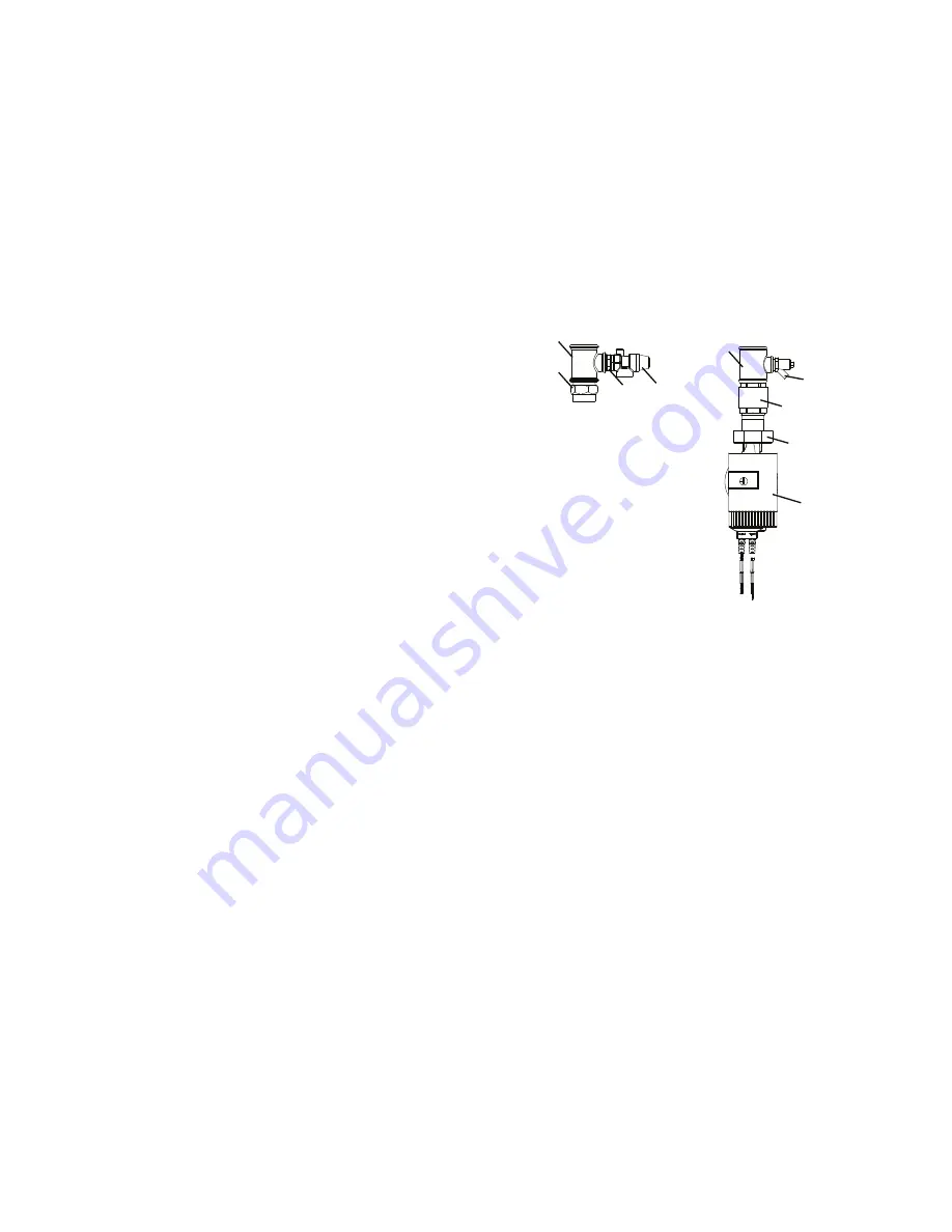
3.6  BOILER CONNECTION KITS

These boiler connections are un-insulated and contain the 

following:

LEGEND

1.   Tee 1 

1

/

4

" X 

3

/

4

" X 1 

1

/

4

2.  Brass union 

3

/

4

" X 

3

/

4

"

3.  Safety relief valve 3 bar

4.  1 

1

/

4

" X 

1

/

2

" X 1 

1

/

4

" Tee

5.  Drain plug

6.  Pump fitting

7.  Non return valve

8.  Pump inc. gaskets

9. 1 

1

/

4

" taper male to 1 

1

/

4

" parallel hex adapter

Note. For boiler connection assembly, refer to Frame 5.3

3.7  FREE-STANDING FRAMES

The low height frames are designed to provide a compact floor 

mounted structure capable of having any of the Evomax range of 

appliances fitted to them. Incorporating all the required mountings 

and assembly systems to bolt up to three frames together in a 

side by side format and mount the relevant water and gas heater 

kits.

Provision is also provided to allow the frames to be bolted to the floor.
Note: Floor mounting bolts are NOT provided.

3.8  INSTALLATION AREA AND DIMENSIONS

Care must be taken to ensure adequate access for boiler / 

cascade system installation and servicing.

A minimum of 450mm must be provided from the front of the 

installed boilers to facilitate boiler servicing.

Consideration to connecting heating flow and return pipework, 

gas supply and condensate drainage must be given.  Routing 

of the condensate drain must be made to allow a minimum fall 

of 1 in 20 away from the installed boilers, throughout its length.  

Adequate room above the boilers must be provided to install and 

service the boiler flue system.  Further information with respect 

to flue and condensate drain connection is provided in the 

installation and servicing instructions provided within the boilers 

packaging carton.

3  SYSTEM COMPONENTS

3

2

1

9

FLOW

RETURN

4

5

6

7

8

Note

Isolating Valves 

are fitted to water 

header along with 

flexible connecting 

pipes.

Summary of Contents for DN50

Page 1: ...be assured conform to the safety and performance specification that we require Do not use reconditioned or copy parts that have not been clearly authorised by Ideal For the very latest copy of literature for specification and maintenance practices visit our website www idealcommercialboilers com where you can download the relevant information in PDF format ...

Page 2: ... 2 General Description Of Systems 4 3 System Components 6 4 Installation Drawings For Boiler Systems 8 5 Installation Procedure 10 6 Electrical Connections 14 7 Commissioning And Testing 14 IMPORTANT THESE KITS MUST ONLY BE USED IN CONJUNCTION WITH LOW LOSS HEADERS IDEAL PROVIDE 3 OPTIONAL LOW LOSS HEADER KITS DN50 UIN 209394 DN65 UIN 209395 DN80 UIN 252437 ...

Page 3: ...f products These systems are adapted to incorporate the use of low loss headers and optional sequencer control systems All these kits are supplied with the relevant number of energy efficient pumps and necessary parts needed to connect these kits to the separately purchased Evomax appliances Check the kit contents with the list below UNPACKING Kit Contents Frame Water Header Hardware Pack Connecti...

Page 4: ...cessories DN50 DN65 DN80 209394 209395 252437 Note All boilers need to be sized in accordance to the total required heat load and the modulation capabilites of the appliances Note When fitted with 150 appliance D 666 from rear frame bolt to front of boiler A single boiler system is defined as fitting one appliance on a single frame with a DN50 water header A two and three boiler system cascade is ...

Page 5: ...let to be made up to the gas tap provided connecting it to the inlet of the appliance 2 and 3 boiler units will be supplied with a 2 gas header and all the necessary components and pipe work to connect it to the appliances Note Test points are provided at each end of the 2 gas header The test point nearest to the gas inlet is intended to be used as the appliance inlet pressure point 2 6 ASSEMBLY T...

Page 6: ...0 209394 DN 65 209395 DN 80 252437 3 5 BOILER SHUNT PUMP The pumps supplied with these kits are design to provide the optimum flow around the appliance water circuit ensuring the maximum flow rates are contain within the design constrains of the appliance It is not recommended to fit additional pumps directly to the appliance circuit unless they have been designed to ensure the maximum permissible...

Page 7: ...eader Kits IMPORTANT POINTS Before commencing installation MOUNTING FRAME S MUST STAND ON A FLAT AND LEVEL FLOOR WHEN ASSEMBLING THE HEADER KIT THE HEADER MUST BE BOLTED TO THE FRAME BEFORE THE FLEXIBLE HOSE CONNECTIONS ARE MADE ...

Page 8: ... 4 1 GENERAL The boiler systems are available in side by side format 1 to 3 boilers in a linear configuration mounted on a free standing frame These boiler and cascade systems are sized to provide a flow and return differential of 20º T 4 2 INSTALLATION DRAWING WITH 1 30 150 BOILER ...

Page 9: ...9 EVOMAX Low Height Frame Header Kits 4 3 INSTALLATION DRAWING WITH 2 30 150 BOILERS 4 4 INSTALLATION DRAWING WITH 3 30 150 BOILERS ...

Page 10: ...ace the frame kit sections in the required position and bolt them together at the top and bottom with the bolts nuts and washers provided 2 Drill and fit the required floor bolt s not provided through the hole provided in the front of the frame feet Note this must be done before fitting water headers 2 1 ...

Page 11: ...fe place See appliance manual 5 Fit condensate trap and pipe work See appliance instruction pipe runs must have 1 20 slope away from the appliance 6 Fit gas connection tap 7 Fit tee with pre assembled non return valve and pump union to the return ensuring the flow arrow is point toward the base of the appliance 8 Attach the drain tap to the return tee ensuring the connection and activation point a...

Page 12: ...mp connection is fitted 2 Check taps are operational 3 Fit water header blanking flanges and gaskets 1 Fit the blanking cap to the required end 2 Fit female to 22 compression fitting to stub pipe on the side of the gas header 3 Place the gas header in the pre cut cradle to the rear of the header 2 1 2 3 ...

Page 13: ...rmally control by associated control sequencers 1 Locate header into required position on the frame legs 2 Align bolt holes and fit bolts loosely 3 Connect the return pump union to the pump ensuring the correct rubber washer is used 4 Connect the flow connector to the boiler flow pipe adaptor ensuring the fibre washer provided is correctly fitted 5 Tighten the heater bolts on to the frame 6 Ensure...

Page 14: ...shunt pumps are wired to the boiler in order to ensure the boiler pump overrun facility is provided 1 Electrical and gas safety checks must be carried out on completion of installation as with individual boiler commissioning 2 Pump setting adjustment Follow instructions on pump type shown below Adjust red control potentiometer fully clockwise to position 8 as shown below This is the constant press...

Page 15: ...15 EVOMAX Low Height Frame Header Kits ...

Page 16: ...sues a policy of continuing improvement in the design and performance of its products The right is therefore reserved to vary specification without notice The Ideal Boilers Technical Training Centre offers a series of first class training courses for domestic commercial and industrial heating installers engineers and system specifiers For details of courses please ring 01482 498 432 Ideal Installe...

Reviews: