12
Concord CXC -
Installation
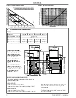
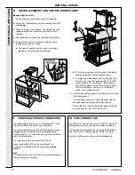
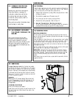
Manoeuvring the boiler
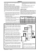
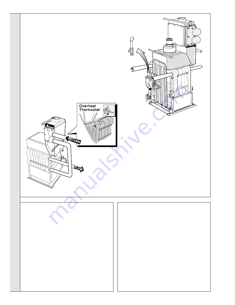
1. Remove the gas cock to access the LHS tapping.
2. Screw the 2 handling bars (2" pipe supplied) into the 2
top tappings.
3. Screw in 2 bars (not supplied), 1 into the LH rear top
tapping and the second into the tee at the RH top
tapping.
4. Use these bars to manoeuvre the boiler into position.
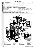
5. Complete the system connections, using suitable
jointing compound, as follows:
a. The flow connection must be made to the upper
tapping on the primary heat exchanger.
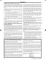
10 FLUE CONNECTION
The 150mm (6") flue should conform to BS.715: Section 2
Stainless Steel or be of equivalent corrosion resistance.
The flue must be designed to have no greater resistance
than that of 30m of straight, smooth 150mm (6") pipe.
All joints must be impervious to condensate leakage.
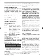
The condensate drain must be 1
1/4
" diameter PVC pipe
from the pre-fitted drain at the rear of the boiler.
The condensate drain may be led directly into the normal
drainage system. The pipe should be installed with an
adequate slope (e.g. 1 in 50) and consideration should be
given to frost protection.
The drain should be in accordance with IM 22.
Connections to BS.5355 can be used directly, or
connections to BS.5354 may be used with a suitable
adaptor.
Note.
A condensate trap is built into the boiler sump therefore an
external trap is not necessary.
b. The return connection must be made to the upper
tapping on the secondary heat exchanger.
c. Complete the water connections by plugging the 2
front top and 1 rear top tappings with the 2" BSP
plugs provided. The remaining 1" lower tapping
should be plugged if not used for cold feed on an
open vent system or connection of a pressure
vessel, if on a sealed system.
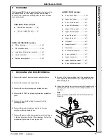
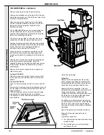
3. Position the overheat thermostat phial into the LH side
thermostat pocket.
The illustration shows the rear of the boiler with the
flow and relative overheat thermostat position.
Ensure that the overheat thermostat phial is correctly
secured in the pocket. Refer to Frame 13.
8
BOILER ASSEMBLY AND SYSTEM CONNECTIONS
INST
ALLA
TION
INSTALLATION
9
CONDENSATE DRAIN CONNECTION
Summary of Contents for Concord CXC 116
Page 1: ......
Page 38: ...38 Concord CXC Installation NOTES ...


