background image

20


Installation and Servicing

SECTION 2 - INSTALLATION
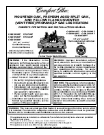
2.8  EXTERNAL WIRING


L

  N 

Room 

Stat 


Frost  


Stat  


DIAGRAM A:                        

Programmable Room Stat or 

Room Stat with Internal Timer

DIAGRAM B:                        

Room Stat with External Timer


Mains In


DIAGRAM C:                        

Use of General Live for Room Stat 

Optional Room Stat / 

Programmable Timer

Optional Frost Stat

Optional Room Stat / 

Programmable Timer

Optional Frost Stat

Optional Frost Stat

L

  N 

Frost  

Stat  

Room 

Stat 

Room Stat with timer

L

N

Stat  

Room 

Stat 

Frost  


L

  N 

Room 

Stat 


Frost  


Stat  


DIAGRAM A:                        

Programmable Room Stat or 

Room Stat with Internal Timer

DIAGRAM B:                        

Room Stat with External Timer


Mains In


DIAGRAM C:                        

Use of General Live for Room Stat 

Optional Room Stat / 

Programmable Timer

Optional Frost Stat

Optional Room Stat / 

Programmable Timer

Optional Frost Stat

Optional Frost Stat

L

  N 

Frost  

Stat  

Room 

Stat 

Room Stat with timer

L

N

Stat  

Room 

Stat 

Frost  


DIAGRAM D:


OpenTherm Device

DO NOT CONNECT 230V TO THESE

TERMINALS OR THE HIU ELECTRONICS

WILL BE DAMAGED

Outside

Sensor

Open

Therm  

OpenTherm Device

E.G. Honeywell OT

Bridge R8810

External Controls – 230V 50Hz

Wiring a 230Vac 50Hz Room thermostat, 
Diagram A (with optional timer, Diagram 
B)

1.  Connect the external cable from the 

room thermostat/timer across the 
terminal labelled ‘Room Stat’. See 
Diagram A.

2.  If the room thermostat has 

compensation and requires a neutral 
connection, make this connection to 
the fused spur on the load side. See 
Diagram C.

Optional External Controls – Extra Low 
Voltage

Wiring OpenTherm Room Control or other 
OpenTherm Master Device, Diagram D.

1.  Connect the two OpenTherm cables 

from the external OpenTherm 
controller into the terminals labelled 
‘OpenTherm’. See Diagram D.

2.  Ensure no other controllers are 

connected to the High Voltage 
‘Room Stat’ connection as this will 
prevent the HIU/OT+ communication 
functioning correctly. 

Frost Protection

If parts of the pipework run in areas subject 
to cold temperatures or if the HIU will be left 
in the ‘Off’ state for more than a 1-day period 
a frost thermostat should be wired into the 
system. The frost thermostat should be sited 
at coldest point in a system such that I can 
sense heat from the system.

Wire a system frost thermostat to the 
terminals labelled ‘Frost Stat’ as detailed in 
diagrams A, B and C. 

2.7  INSTALLER WIRING

The image below shows the HIU electrical connections. 

The HIU must be connected to a permanent live supply via the 
‘L’ ‘N’ and ‘GND’ connections and not switched by thermostats/
programmers. The installer wiring must be inserted through the 
rubber grommets in the base of the HIU and securely clamped 
by the cable retention bars to prevent strain on the terminal block 
connections. 

Accessing the installer wiring
1. 

Isolate the mains supply from the HIU.

2. 

Open the drop-down cover and remove the front access 
panel. Refer to Section 3.4.

3. 

Gently swing down the control box into the service position 
to expose the installer connections. 

All the installer connections can now be easily accessed. Once 
any wiring is complete, to ensure the HIU is safe, rebuild the 
unit in the reverse order above.

ROOM 

  STAT

FROST 

  STAT

N

L

OUTSIDE

SENSOR

OPEN

THERM

MBUS

INST

ALLA

TION

Summary of Contents for i305

Page 1: ...rts that have not been clearly authorised by Ideal Heating For the very latest copy of literature for specification and maintenance practices visit our website idealheating com where you can download...

Page 2: ...2 Installation and Servicing...

Page 3: ...03 July 21 Updated images additional Section 3 17 Domestic Hot Water Thermistor Ideal Heating reserve the right to vary specification without notice FOR ANY TECHNICAL QUERIES PLEASE RING THE IDEAL INS...

Page 4: ...4 Installation and Servicing...

Page 5: ...NG 29 3 1 Servicing Schedule 29 3 2 Key Components Indirect 30 3 3 Key Components Direct 31 3 4 HIU Front Panel Removal Replacement 32 3 5 Draining The Heat Interface Unit 32 3 6 Primary Strainer Remo...

Page 6: ...to operate at 0 6 bar system pressure bar PSI kPa 0 5 bar 7 25 50 Maximum Operational DHW Temperature dependant on primary supply C 65 C 70 C to 85 C Primary Maximum Primary Supply Pressure bar PSI k...

Page 7: ...min 9 7 13 3 16 7 19 0 22 4 9 7 13 3 16 7 19 0 DHW Output 55 C 45K rise kW 30 7 39 9 50 6 57 9 63 4 30 7 39 9 50 6 57 9 Primary Flow Rate l s 0 16 0 21 0 26 0 29 0 32 0 16 0 21 0 26 0 29 Primary Retur...

Page 8: ...has not operated in a 24 hour period the control will operate the valve briefly to prevent the valve from becoming stuck in position Construction the HIU casing and front door is of white painted mil...

Page 9: ...be made to the current ETCI rules for electrical installation Detailed recommendations are contained in the following British Standard Codes of Practice CIBSE CP1 2020 Heat Network code of practice B...

Page 10: ...le isolator and where practical replacement installations the isolator shall be situated adjacent to the appliance 0 6m Zone 0 Recessed window Zone 2 Ceiling 3G8913a 2 25m Zone 1 Compartment Installat...

Page 11: ...25mm from the outward opening cupboard door 600mm overall clearance is still required with a cupboard door open to allow for servicing Bottom Clearance The bottom clearance from the underside of the w...

Page 12: ...m and maximum working pressures In areas of low mains water pressures the domestic hot water regulator may be removed from the DHW flow turbine manifold Refer to Section 3 21 The HIU will require the...

Page 13: ...the Guidance Notes on Water Treatment in Central Heating Systems If water treatment is used Ideal Heating recommend only the use of SCALEMASTER SM 1 PRO FERNOX MBI ADEY MC1 SENTINEL X100 or CALMAG CM1...

Page 14: ...Primary Flow Pipe DHW 2 131 Primary Flow Pipe CH 1 132 Primary Flow Pipe CH 2 133 Primary Return Pipe 136 CH Flow Pipe Indirect 137 CH Return Pipe Indirect 138 CH Return PIPE Direct 139 CH Flow Pipe...

Page 15: ...damage to the pressure relief out pipe and valve Care MUST be taken to support the appliance during lifting This should be done by 2 people due to the weight of the unit DO NOT LIFT THE APPLIANCE VIA...

Page 16: ...horizontal c Remove brass plugs from the top of the isolation valves if used Discard any used gaskets 4 Lift the HIU onto the wall mounting plate refer to the Introduction section for safe handling a...

Page 17: ...the dust cap from valve A and plug from the filling loop adjacent to valve A 3 Ensure top hat washers is still fitted to the valve A if not then check inside the removed dust cap 4 Connect the filling...

Page 18: ...n section 3 12 to gain access to the Primary and CH Air Vents 2 Ensure isolation valves C D E and F are in closed position handle horizontal 3 Turn the black handle on isolation valve D so it is point...

Page 19: ...pole switch having 3mm contact separation in both poles The means of isolation must be accessible to the user after installation WARNING This appliance MUST be earthed All electrical work within the u...

Page 20: ...ostat has compensation and requires a neutral connection make this connection to the fused spur on the load side See Diagram C Optional External Controls Extra Low Voltage Wiring OpenTherm Room Contro...

Page 21: ...al Turbine GND Turbine 5V WPS Signal WPS GND WPS 5V DHW Valve Q1 Q3 DHW Valve Q2 Q4 DHW Valve Q5 Q7 DHW Valve Q6 Q8 CH Valve Q1 Q3 CH Valve Q2 Q4 CH Valve Q5 Q7 CH Valve Q6 Q8 MAINS LIVE MAINS NEUTRAL...

Page 22: ...ll the relevant parameters to provide efficient operation of the HIU and the Heat Network A B C D E F G Electrical Installation 1 Checks to ensure electrical safety should be carried out by a competen...

Page 23: ...ed limits Note If using underfloor heating ensure CH target temperature is within the safe operating temperature for the underfloor heating Switching CH On Off Press the Menu button again to access th...

Page 24: ...W demand the display will show the tap symbol and the DHW delivery temperature With a CH demand the display will show the radiator symbol and the CH delivery temperature If Preheat is enabled the HIU...

Page 25: ...lowing options II Indirect indirect dI Direct indirect It N A Dt N A Press the Menu button when the correct option is selected Press the button to cycle through the following options Indirect II 30 40...

Page 26: ...s Press the Menu button to progress to the DHW Valve Replacement service mode If buttons are pressed the DHW valve will drive fully open for up to 30 minutes This may be required if the valve body nee...

Page 27: ...activation display Press buttons to enable disable the primary return limitation function Note This function is independent of the Credit control valve accessory behaviour Press the Menu button again...

Page 28: ...es under the relevant national regulations 2 Explain and demonstrate the start up and shutting down procedures 3 The operation of the HIU and the use and adjustment of all system controls should be fu...

Page 29: ...er to Section 4 fault finding as necessary Warning Always isolate all service valves switch off and disconnect the electrical supply to the appliance before servicing 5 Check the DHW filter for blocka...

Page 30: ...rimary Return Assembly 9 Manifold DHW Flow Assembly 10 Manifold DCW Assembly 11 PICV DN20 12 PICV DN15 13 Air Vent DCW 14 Air Vent Primary 15 Air Vent CH 16 PRV 17 Auto Air Vent 18 Pump Head 19 Pressu...

Page 31: ...t CH 7 Manifold Primary Flow Assembly 8 Manifold Primary Return Assembly 9 Manifold DHW Flow Assembly 10 Manifold DCW Assembly 11 PICV DN20 12 PICV DN15 13 Air Vent DCW 14 Air Vent Primary 15 Air Vent...

Page 32: ...imary circuit both flow and return isolation valves MUST be isolated Failure to do this will subject the drain point to system pressure when opened and cause the full system to be drained NOTE INDIREC...

Page 33: ...be engaged 4 Check that the HIU operates in both DHW CH modes 3 7 CH PRESSURE GAUGE REPLACEMENT INDIRECT ONLY 1 1 Isolate and drain primary circuit refer to Section 3 5 2 Refer to Section 3 4 for fron...

Page 34: ...pansion vessel 11 Fit the new expansion vessel 12 Reassemble in reverse order ensuring the seal is in place 13 Refill the HIU and check for leaks Refer to Section 2 5 14 Check that the HIU operates in...

Page 35: ...e HIU operates in both DHW CH modes 3 11 PUMP AUTOMATIC AIR VENT REMOVAL REPLACEMENT 1 Refer to Section 3 4 for front panel removal 2 Isolate and drain the HIU Refer to Section 3 5 3 Remove the expans...

Page 36: ...TION FRONT SECTION REMOVAL REPLACEMENT 1 Refer to Section 3 4 for front panel removal 2 Remove harness from the insulation channel and lower down 3 Remove front insulation section by pulling forward a...

Page 37: ...heir outlets facing left and right and the 2 x 60 elbows are fitted with their outlet facing downwards Note Failure to correctly locate the poisition of the elbows will prevent the retention clips fro...

Page 38: ...ws are fitted with their outlet facing downwards Note Failure to correctly locate the poisition of the elbows will prevent the retention clips from being fitted 11 Ensure new retention clips are locat...

Page 39: ...er provided 6 Reassemble in the reverse order 7 Refill the HIU Refer to Section 2 5 8 Check that the HIU operates in both DHW CH modes 1 Isolate and drain the HIU Refer to Section 3 5 2 Remove the fro...

Page 40: ...ould be used 6 Fit the new thermistor 7 Reassemble in the reverse order 8 Refill the HIU Refer to Section 2 5 9 Check that the HIU operates in both DHW CH modes 3 17 DOMESTIC HOT WATER THERMISTOR 3 18...

Page 41: ...and pull the PRV upward to remove it from the manifold 5 Reassemble in reverse order ensuring the retaining clip is correctly fitted the pipe compression fitting re tightened and return thermistor is...

Page 42: ...at the mains wait for 10 seconds and power on again d Display shows F9 e Press the or button to progress to the HIU type setting screen f Using the or button the display will be able to by cycled betw...

Page 43: ...nd drain down the HIU Refer to Section 3 5 2 Remove the front panel Refer to Section 3 4 3 Remove insulation front section Refer to Section 3 12 4 Disconnect the connector on the flow turbine harness...

Page 44: ...the valve The unit must be then turned off at the mains and back on to allow the valve to recalibrate its position 1 Isolate the mains electrical supply 2 Remove the front panel Refer to Section 3 4...

Page 45: ...flow filter manifold 8 Place both halves of the plastic adapter around the 3 notches of the temperature sensor 9 Press the adapter together and screw hand tight 3 5 Nm into the primary flow filter ma...

Page 46: ...eaks 17 Activate the meter and follow the heat meter instructions provided to commission and setup the meter 18 Ensure control box cover can move freely and the front panel can be secured without trap...

Page 47: ...THIS PAGE HAS BEEN LEFT INTENTIONALLY BLANK...

Page 48: ...on flow thermistor and using a multi meter measure the resistance of the thermistor This should be around 10k in ambient conditions If thermistor is functioning correctly reconnect harness to flow th...

Page 49: ...using the process as shown in Section 3 20 HOT WATER PREHEAT fp OFF Pump Failure Check system water pressure is between 1 and 1 5 bar on the system pressure gauge If system pressure is low increase th...

Page 50: ...pplied to the HIU Replace PICV as shown in Section 3 24 NO NO NO NO YES YES YES YES No CH operation but DHW OK Is the Tap symbol shown on the display during a DHW demand Ensure the wiring between the...

Page 51: ...ter Pressure Sensor Fault F1 No CH operation 11 DHW Sensor disconnected from pipe FC DHW Valve to closed position 51 Low Water Pressure F1 No CH operation 63 High Mains Voltage N A N A 64 Low Mains Vo...

Page 52: ...eal Failure to do so could affect safety or performance of this appliance Comprehensive spares parts information and details of approved Ideal Parts Distributors are available on idealheating com Our...

Page 53: ...res Has a domes c hea ng system lter been installed Yes No CENTRAL HEATING MODE measure and record for direct appliances record only primary ow return in central hea ng mode Primary di eren al pressur...

Page 54: ...ure checked adjusted Yes CH system expansion vessel pressure checked adjusted Yes CH system ll pressure checked adjusted as necessary Yes CH system ll pressure checked adjusted as necessary Yes DHW Co...

Page 55: ...ure checked adjusted Yes CH system expansion vessel pressure checked adjusted Yes CH system ll pressure checked adjusted as necessary Yes CH system ll pressure checked adjusted as necessary Yes DHW Co...

Page 56: ...ufactured under an ISO 9001 registered quality management system FM 59915 At Ideal Heating we take our environmental impact seriously therefore when installing any Ideal Heating product please make su...

Reviews: