34
Viscount GTS -
Installation & Servicing
INSTALLATION
220
90
VIS5112
1
2
3
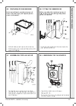
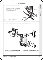
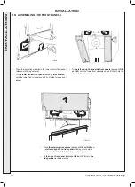
• Place the side insulating material against the positioning
bracket (1) and cut it so that it is flush with the upper lug on
which the rail fastening bracket is fixed, along a 220 mm
length (2).
• (3) Push the insulating material in behind the lug and the rail
fastening bracket.
• Distribute the insulating material evenly so that you have the
same side insulating material on either side of the boiler.
• Cut the material similarly along the fastening brackets.
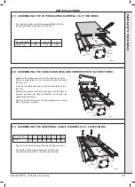
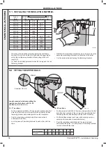
52 FITTING THE UPPER RAILS
A
REAR
FRONT
VIS5113
14 - 17 sections
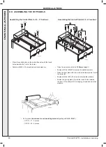
• Fix the upper rail with M8 x 30 screws and washers (the first
hole from the front end of the rail must be opposite the first
fastening bracket, and similarly with the other brackets).
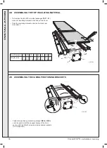
• Push the insulating material behind the lower rail and
underneath the boiler.
• Join the pieces of insulating material to each other with the
clips.
18 - 25 sections
• Fix the upper rail with M8 x 30 screws and washers (the first
hole from the front end of the rail must be opposite the first
fastening bracket, and similarly with the other brackets).
•
Fix the additional upper and lower rails, making sure you
comply with dimension A (see table below).
• Push the insulating material behind the lower rail and
underneath the boiler. Join the pieces of insulating material
to each other with the clips.
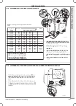
Length required while assembling the
two-piece rails (boilers with 18 - 25
sections)
(see table below).
No. of Sections
18 19 20 21 22 23 24
25
A (mm)
2500 2615 2765 2875 2965 3075 3165 3275
Type of
Boiler
GTS 14
1200
600
GTS 15
1200
400
400
GTS 16
1200
400
600
GTS 17
1200
400
600
GTS 18
1200
1200
GTS 19
1200
1200
GTS 20
1200
400
400
600
GTS 21
1200
400
1200
GTS 22
1200
400
1200
GTS 23
1200
600
1200
GTS 24
1200
600
1200
GTS 25
1200
400
400
1200
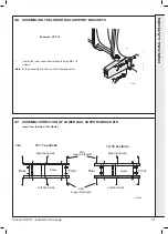
Side insulating material (length in mm)
FRONT
REAR
Example: GTS 16
51 INSTALLING THE INSULATING MATERIAL
INST
ALLA
TION


