background image

Classic 

FF

 - 

Installation & Servicing

7

GENERAL

2. If the boiler is to be installed in a cupboard or compartment,

permanent air vents are required (for cooling purposes) in
the cupboard/compartment, at both high and low levels.
The air vents must either communicate with room/internal
space, or be direct to outside air. The minimum effective
areas of the permanent air vents, required in the cupboard/
compartment, are specified in Table 4 and are related to
maximum rated heat input.

3. Both air vents MUST communicate with the same room or

internal space or MUST be on the same wall to outside air.

4. In siting the air vents care must be taken to avoid the

freezing of pipework.

WATER CIRCULATION SYSTEM

The boiler must NOT be used for direct hot water supply. For the
types of system and correct piping procedure refer to 'Introduction'
and Frame 1.

The central heating system should be in accordance with BS.6798
and, in addition, for Smallbore and Microbore systems, BS. 5449.

The domestic hot water system, if applicable, should be in
accordance with the relevant recommendations of BS. 5546. Copper
tubing to BS. 2871:1 is recommended for water carrying pipework.

The hot water storage cylinder MUST  be of the indirect type and
should preferably be manufactured of copper.

Single feed, indirect cylinders are not recommended and MUST
NOT be used on sealed systems.

The appliances are NOT suitable for gravity central heating, nor
are they suitable for the provision of gravity domestic hot water.

The hot water cylinder and ancillary pipework, not forming part of
the useful heating surface, should be lagged to prevent heat loss
and any possible freezing - particularly where pipes run through
roof spaces and ventilated under floor spaces.

Boilers not fitted to a sealed  system must be vented.

IMPORTANT

A minimum length of 1m of copper pipe MUST be fitted to both
flow and return connections from the boiler before connection to
any plastic piping.  This applies to ALL types of installation.

Draining taps MUST be located in accessible positions, which
permit the draining of the whole system - including the boiler
and hot water storage vessel. They should be at least 

1/2" BSP

nominal size and be in accordance with BS. 2879.

The boiler is fitted with a special drain plug, which is provided, to
drain the BOILER ONLY, in the event of the system drain plug
being unable to do so. The hydraulic resistance of the boilers, at
MAXIMUM OUTPUT with an 11

O

C (20

O

F) temperature differential,

are shown in Table 5.

Maximum boiler operating temperature should be 82 

o

C (180 

o

F).

WATER TREATMENT

These boilers incorporate a cast iron heat exchanger.

IMPORTANT. The application of any other treatment to this
product may render the guarantee of Caradon Ideal Limited
INVALID.

Caradon Ideal Limited recommend Water Treatment in
accordance with the 

Benchmark Guidance Notes on Water

Treatment in Central Heating Systems.

Caradon Ideal Limited recommend the use of Fernox, GE Betz
Sentinel or Salamander water treatment products, which must
be used on accordance with the manufacturers instructions.

For further information contact:

Fernox Manufacturing Co. Ltd, Cookson Electronics, Forsyth Road,
Sheerwater, Woking, Surrey.   GU21 5RZ.  Tel. +44 (0) 1799 521133

or

G E Betz Ltd, Sentinel Division, Foundry Lane, Widnes, Cheshire,
WA8 8UD.  Tel. +44 (0) 151 424 5351

or

Salamander Engineering Ltd, Unit 24, Reddicap Trading Estate,
Sutton Coldfield, West Midlands B75 7BU.  Tel. +44 (0) 121 378 0952

Notes.

1. It is most important that the correct concentration of the water

treatment products is maintained in accordance with the
manufacturers' instructions.

2. If the boiler is installed in an existing system any unsuitable

additives MUST be removed by thorough cleansing.
BS7593:1992 details the steps necessary to clean a
domestic heating system.

3. In hard water areas, treatment to prevent limescale may be

necessary - however the use of artificially softened water is
NOT permitted.

4. Under no circumstances should the boiler be fired before

the system has been thoroughly flushed.

BOILER CONTROL INTERLOCKS

Caradon Ideal Limited recommend that heating systems utilising
full thermostatic radiator valve control of temperature in individual
rooms should also be fitted with a room thermostat controlling the
temperature in a space served by radiators not fitted with such a
valve as stated in BS. 5449.
Central heating systems controls should be installed to ensure the
boiler is switched off when there is no demand for heating or hot water.
When thermostatic radiator valves are used, the space heating
temperature control over a living / dining area or hallway having a
heating requirement of at least 10% of the boiler heat output should
be achieved using a room thermostat, whilst other rooms are
individually controlled by thermostatic radiator valves. However, if
the system employs thermostatic radiator valves on all radiators,
or two port valves without end switches, then a bypass circuit must
be fitted with an automatic bypass valve to ensure a flow of water
should all valves be in the closed position.

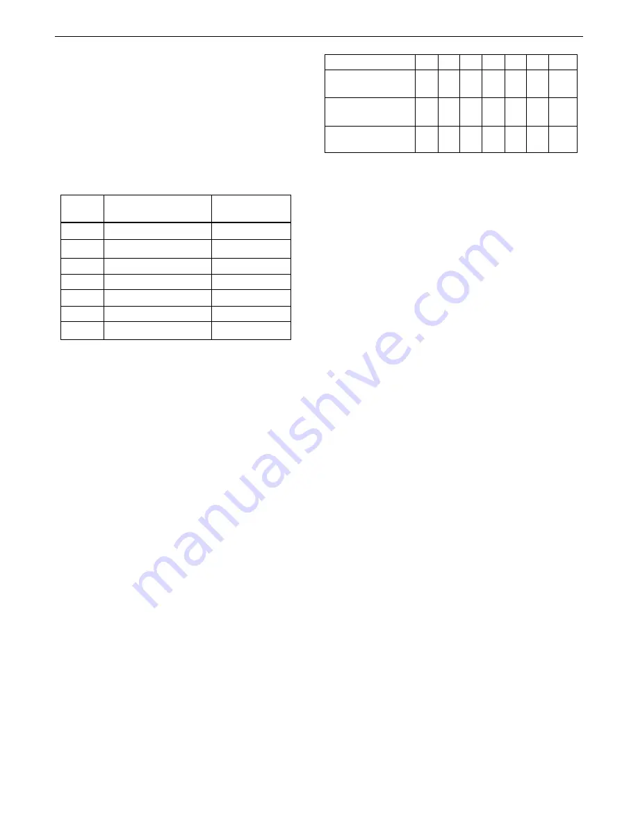
Table 4 - High and low vent areas

Boiler

Air from room/internal

Air direct from

space, cm (in

2

 )

outside, cm (in

2

)

FF330

 102

(16)

 51

(8)

FF340

135

(21)

 68

(11)

FF350

170

(26)

 83

(13)

FF360

198

(31)

 102

(16)

FF370

231

(36)

116

(18)

FF380

264

(41)

132

(21)

FF3100

340

(52)

170

(26)

Boiler Size

FF

330

340

350

360

370

380

3100

Boiler

kW  8.8 11.7 14.6 17.6 20.5 23.4 29.3

Output Btu/h x 1000

30

40

50

60

70

80

100

Water Flow

l/min 11.4 15.2 19.0 22.8 26.5 30.3 38.0

Rate

gal/h 150 200 250 300 350 400 500

Pressure

mbar 22.0 20.4 31.5 41.7 54.8 77.0 106

Loss

in  wg  8.9  8.3 12.6 16.7 22.0 30.9 42.5

Table 5 - Water flow rate and pressure loss

Summary of Contents for FF 330

Page 1: ...EERED FOR PEACE OF MIND When replacing any part on this appliance use only spare parts that you can be assured conform to the safety and performance specification that we require Do not use reconditio...

Page 2: ...m 28mm copper copper FEMALE Maximum static water head m ft 30 5 100 Minimum static water head m ft 0 45 1 5 Electrical supply 230 V 50 Hz Boiler power consumption 100W Fuse rating External 3A Internal...

Page 3: ...07 Destination Countries GB IE Models G C Appliance No Classic FF 330 41 391 54 Classic FF 340 41 391 95 Classic FF 350 41 391 96 Classic FF 360 41 391 97 Classic FF 370 41 391 98 Classic FF 380 41 39...

Page 4: ...eal Limited could invalidate the BSI Certification and the normal appliance warranty It could also infringe the Gas Safety Regulations and the above regulations SAFE HANDLING OF SUBSTANCES Care should...

Page 5: ...ns packed with the unit for the necessary clearances Pelmet restrictions If the ability to fit or remove the casing during installation and subsequent servicing is impaired by pelmets etc this operati...

Page 6: ...ngs are specified in Table 3 4 Where the lowest part of the terminal is fitted less than 2m 6 6 above a balcony above ground or above a flat roof to which people have access then the terminal MUST be...

Page 7: ...al Limited INVALID Caradon Ideal Limited recommend Water Treatment in accordance with the Benchmark Guidance Notes on Water Treatment in Central Heating Systems Caradon Ideal Limited recommend the use...

Page 8: ...Limited Note A cold water feed must be available back to the boiler when all automatic valves are in the closed position refer to BS 6798 and when close coupled the feed must not be in a vertical leg...

Page 9: ...overing at least the range 0 4 bar 0 60 lb in2 must be fitted to the system The gauge should be easily seen from the filling point and should preferably be connected at the same point as the expansion...

Page 10: ...n automatic air vent connected between them the stop valve being located between the system and the automatic air vent The stop valve may remain open during normal operation of the system if automatic...

Page 11: ...shown LEGEND 1A Heat exchanger 2 Flue baffles 3 Tie rods 4A Pumped flow pipe 5A Pumped return pipe 6 Collector hood assembly 7 Combustion chamber 12 Main burner 19 Control box 24 Pressure switch 30 F...

Page 12: ...1 off No 8 x 8 lg Pozi pan hd screws 3 off 8 UNPACKING Pack A Contents The complete boiler Installation Servicing Instructions User s Instructions Hardware Pack listed below Wall mounting template Wal...

Page 13: ...d Pack D optional extension kit for side flue or rear flue outlet Refer to Frame 33 1 A maximum of 2 extension ducts plus the standard flue duct may be used together 2 Flue extensions of greater than...

Page 14: ...n 3 Ensure squareness by hanging a plumb line as shown 4 Mark onto the wall if required the following a The wall mounting plate screw positions choose one from each group Note Mark the centre of the f...

Page 15: ...uct Ensure the boiler sealing ring is fully engaged Ensure the notch aligns with the groove on the outer flue duct This ensures correct alignment of the flue terminal 4 Stick the self adhesive foam st...

Page 16: ...boiler 1 Lift the boiler onto the wall mounting plate hooks as shown Do not use the burner controls for lifting 2 Fit the M8 screw washer and rectangular plate to retain the boiler Note Before fully t...

Page 17: ...hole has been accurately cut with a drill then making good the wall faces is not essential as seals are provided at both ends of the flue However both wall faces immediately around the cut hole should...

Page 18: ...s cut square mark the flue all the way round 4 Insert the cardboard duct ring for support and cut to length 5 Remove cardboard duct ring and remove any burrs 26 FITTING BOILER SEALING RING TO THE FLUE...

Page 19: ...s is required then the downward routing pipe brackets and M8 spacer supplied in the Downward Piping Kit should be fitted to the wall mounting plate now 3 Fit the bottom 2 screws to secure the bracket...

Page 20: ...to the fan 5 Pull the flue extension tube and engage onto the fan elbow and secure with the screw attached to the elbow Note The sealing ring studs will locate in the back panel one way only This will...

Page 21: ...for FF 3 100 model 35 FITTING THE KIT 1 Remove the cardboard support aid from the flue and place safely to one side 2 Fit the inner flue extension duct onto the inner flue duct 3 Fit the outer flue ex...

Page 22: ...to Frame 43 3 If a proprietary system is used follow the instructions supplied by the manufacturer 4 System designs featuring controls or wiring arrangements which allow the boiler to fire when there...

Page 23: ...led system set the boiler thermostat to maximum 4 Switchmaster Midi is similar in operation but the wiring differs slightly see the manufacturer s literature 40 PICTORIAL WIRING 41 MID POSITION VALVE...

Page 24: ...e left off for more than a day or so then a frost thermostat should be wired into the system This is usually done at the programmer in which case the programme selector switches are set to OFF and all...

Page 25: ...servicing position See diagram B 4 Slacken the screw in the burner pressure test point F and connect a gas pressure gauge via a flexible tube 5 Swing the control box back into its working position 6 P...

Page 26: ...002 10 Stress the importance of regular servicing by a CORGI registered installer and that a comprehensive service should be carried out AT LEAST ONCE A YEAR In IE servicing work must be carried out b...

Page 27: ...e LH bottom rear of the burner and pull the burner downwards to disengage the retention tab Remove the burner to a safe place for inspection and cleaning 2 Remove the control box fixing screw Pull the...

Page 28: ...o the fan Disconnect the connector from the fan and slide into the flue 3b Side or top flue Slacken off two M4 screws securing the flue elbow and flue connector Disconnect the flue connector from the...

Page 29: ...hermostat and reassemble in reverse order 6 Check the operation of the boiler 55 GAS PRESSURE ADJUSTMENT PILOT The pilot is factory set to maximum and no further adjustment is possible If after removi...

Page 30: ...sensor lead connector off the printed circuit board and cut the cable strap securing the thermistor harness to the bottom panel of the control box if fitted and remove the strap 6 Remove the sensor f...

Page 31: ...her is replaced when refitting the pilot injector 6 Replace the electrode and pilot shield retaining both with the electrode nut Check the spark gap 7 Reassemble in reverse order 8 Check the operation...

Page 32: ...f the procedure detailed below 1 Refer to Frame 56 2 Remove the burner and air box assembly Refer to Frame 51 3 Remove the electrode retaining nut 4 Remove the pilot shield 5 Remove the ignition elect...

Page 33: ...ts and withdraw from the control box 6 Fit the new PCB and reassemble in reverse order 7 Check the operation of the boiler Fuse To change the fuse prise it out of the holder and disengage the fuse Ref...

Page 34: ...with water pipes and hang it on the key hole slots and screws Retighten the screws 12 Replace the 2 rubber sealing grommets 13 Reassemble in reverse order 14 Remake all water connections ensuring that...

Page 35: ...ked YES Replace gas valve NO Is there a supply on terminals of main gas valve YES NO YES NO NO Is there a supply on the fan connector at PCB Molex marked FAN YES YES NO NO Check the polarity of the ma...

Page 36: ...929 30 Fan assembly E83 665 FF 330 380 1 171 461 E87 032 FF 3100 1 171 462 35 Boiler casing assembly complete with sightglass assy insulation and M5 x 16 dogpoint pozi pan hd FF 330 380 1 171 471 FF...

Page 37: ...Classic FF Installation Servicing 37 LIST OF PARTS cla 6113 45 59 23 12 18 19 30 24 39 9 17 26 15 14 13 13 A 72 SHORT PARTS LIST 73 BOILER CASING ASSEMBLY...

Page 38: ...pilot assembly 12 Main burner 13 Main burner injector 16 Pilot shield 17 Gas control valve 42 Gas service cock 75 BURNER ASSEMBLY Exploded View LEGEND 19 Control box 21 Thermostat potentiometer 23 Pr...

Page 39: ...Classic FF Installation Servicing 39 NOTES...

Page 40: ...cation without notice The Ideal Boilers Technical Training Centre offers a series of first class training courses for domestic commercial and industrial heating installers engineers and system specifi...

Reviews: