Classic Combi FF 280 -
Installation
37
SERVICING
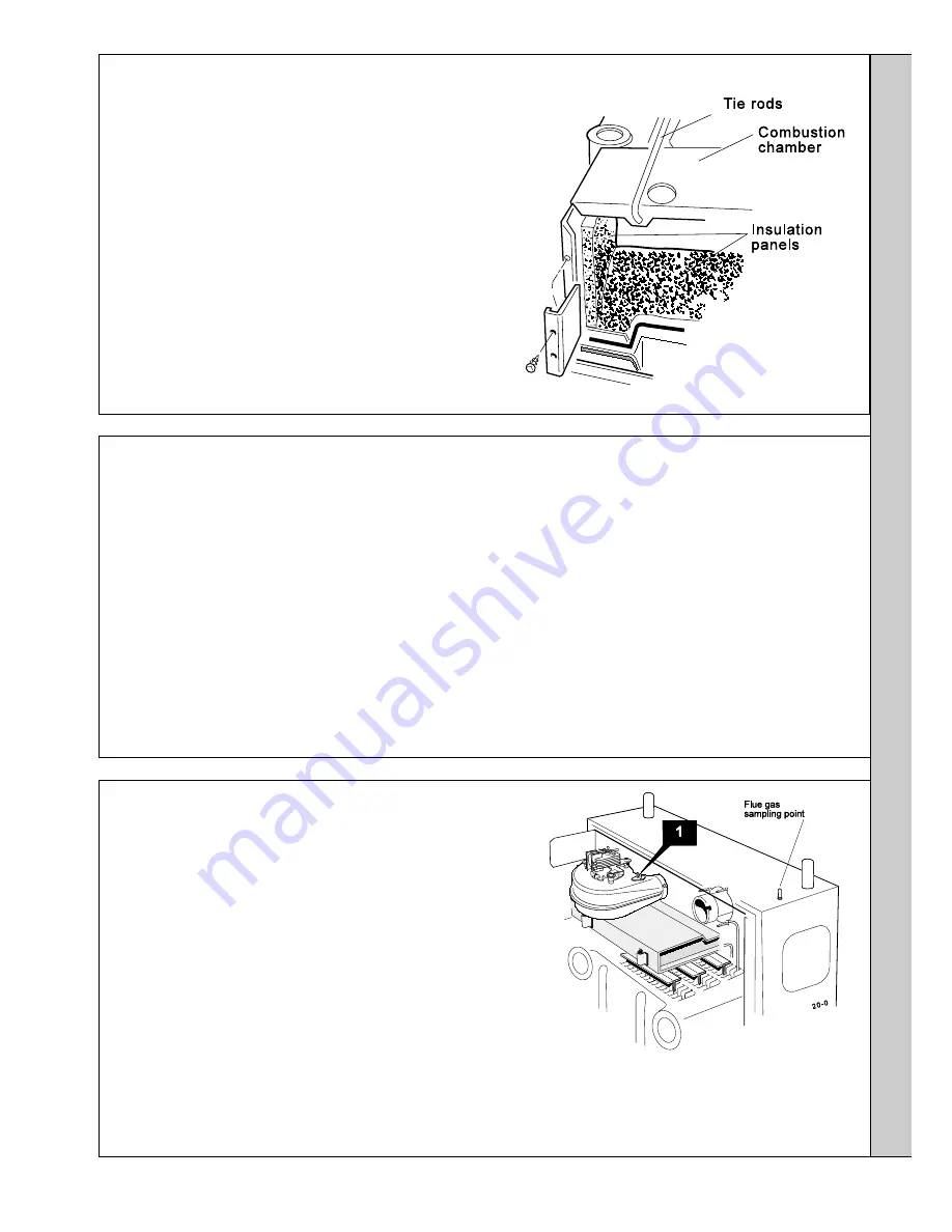
71 COMBUSTION CHAMBER INSULATION REPLACEMENT
1.
Refer to Frame 64
2.
Remove the burner and air box assembly. Refer to Frame 58.
3.
Remove the tie rods and combustion chamber.
4.
Remove the 2 side panel retaining brackets.
5.
Remove the side insulation panels.
6.
Remove the front and rear insulation panels.
7.
Fit the new front and rear insulation panels.
8.
Fit the new side panels and retain with the brackets and
screws previously removed.
9.
Refit the combustion chamber and tie rods.
10
. Re-assemble the rest of the appliance in reverse order.
72 GAS CONTROL VALVE REPLACEMENT
7.
Remove the gas control / manifold assembly.
8.
Remove the 4 screws retaining the manifold to the gas
control valve and fit the manifold to the new gas control
valve. Ensure that the new control is fitted the correct way
round (an arrow engraved on the back indicates the
direction of flow).
Note.
Remove the gas cock stub and refit into the new
gas control valve. Use an approved jointing compound on
the pipe stub.
9.
Reassemble in reverse order.
10.
Replace the boiler casing.
11.
Check the gas valve operation / gas soundness.
SER
VICING
Note.
Also refer to Frames 93 & 94, 'Exploded Views' , for illustration of the procedure detailed below.
1.
Refer to Frame 64.
2.
Remove the burner support bracket, burner and air box
assembly. Refer to Frame 58.
3.
Remove the control box fixing screw. Pull the box
forward and downward to disengage.
4.
Remove the gas control valve electrical connections.
5.
Disconnect and remove the gas union from the gas
control valve.
6.
Whilst supporting the gas control valve, remove the 2
screws retaining the manifold to the back panel.
73 FAN REPLACEMENT
1.
Remove the 2 silicon rubber tubes from the fan sensing points.
2.
Disconnect the fan leads and the fan earth connection.
3a. Rear flue:
Slacken the M4 screw securing the flue connector to the fan.
Disconnect the connector from the fan and slide into the flue.
3b. Side flue:
Slacken off two M4 screws securing the flue elbow and flue
connector. Disconnect the flue connector from the elbow and slide into
the flue. Remove the flue elbow.
4.
Disconnect the silicon rubber tube from the rear of the collector hood.
5.
Slacken the two M5 nuts on the front tie rods, releasing the tie rods from
the combustion chamber.
6.
Remove the M5 central fixing screw at the rear of the collector hood and
remove collector hood/fan assembly.
7.
Remove the three M4 screws retaining the fan to the collector hood.
8.
Reassemble in reverse order, ensuring the fan leads, fan earth
connection and 3 sensing tubes are reconnected.
9.
Refit the boiler casing.
10.
Check the boiler operation.


