

36
British Gas 440 - 480 RD2 -
Installation & Servicing
SERVICING
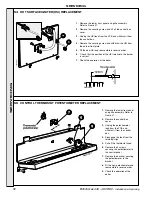
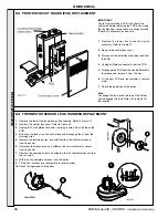
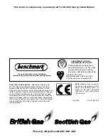
63 PRINTED CIRCUIT BOARD (PCB) REPLACEMENT
IMPORTANT.
Any failure indicating a PCB fault should be
confirmed before replacing the PCB by ensuring
that all electrical connections are correctly made
(Check pin alignment) and secure.
1. Remove the lower front panel and grille
assembly. Refer to Frame 47.
2. Remove the control box cover.
3. Disconnect the detection electrode lead from
the PCB.
4. Unplug all Molex connectors from the PCB.
5. Disengage the PCB from the stand-off brackets
to release and remove it from the box.
6. Fit the new PCB and reassemble in reverse
order.
7. Check the operation of the boiler.
Fuse.
To change the fuse, prise the top off the holder
and disengage the fuse. Refer to Frame 34 for
the location.
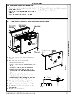
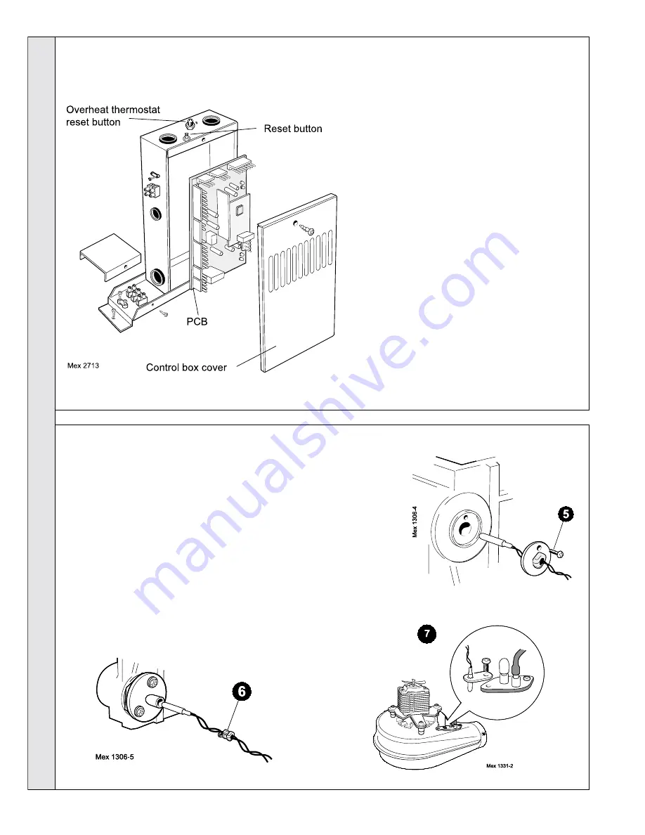
64 THERMISTOR SENSOR LEAD HARNESS REPLACEMENT
1. Remove the lower front panel and grille assembly. Refer to Frame 47.
2. Remove the control box cover. Refer to Frame 63.
3. Unplug the 7-way Molex connector (carrying 6 wires) from the top of the
PCB.
4. Withdraw the leads from the control box and disengage them from the
retaining clips.
5. Remove the retaining screw and withdraw the flow thermistor sensor
from its pocket.
6. Compress the Heyco bush and withdraw the return thermistor sensor
from its pocket.
7. Remove the securing screw and withdraw the fan thermistor sensor from
the fan scroll.
8. Withdraw the complete harness from the boiler.
9. Fit the new harness and reassemble in reverse order.
10. Check the operation of the boiler.
SER
VICING