


10
British Gas 440 - 480 RD2 -
Installation & Servicing
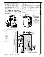
GENERAL
5
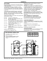
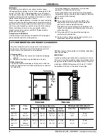
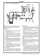
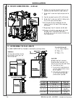
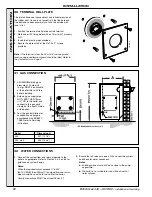
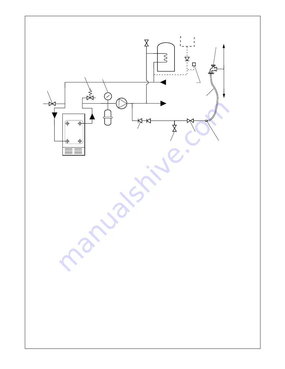
SEALED SYSTEM REQUIREMENTS
Make-up vessel
(max. capacity
3 litres
)
Hose
union
bib
tap
Non-return
valve
Air vent
Water
supply
Pressure gauge
Automatic
air vent
Safety valve
Drain cock
BOILER
Expansion
vessel
Pump
Hose
connector
HEATING
CIRCUIT
Hosepipe
(disconnect
after filling)
BS.1010:2
stop tap
Test cock
Double check valve
Mex
903
Note.
The method of filling, refilling, topping up or flushing
sealed primary hot water circuits from the mains via a
temporary hose connection is only allowed if acceptable to
the local water authority.
1. General
a. The installation must comply with the requirements of
BS.6798 and BS.5449.
b. The installation should be designed to work with flow
temperatures of up to 82
o
C.
c. All components of the system, including the heat
exchanger of the indirect cylinder, must be suitable for
a working pressure of 3 bar (45 lb/in
2
) and temperature
of 110
o
C. Care should be taken in making all
connections so that the risk of leakage is minimised.
2. Safety Valve
A spring loaded safety valve complying with the relevant
requirements of BS.6759 must be fitted in the flow pipe, as
close to the boiler as possible and with no intervening valve
or restriction. The valve should have the following features:
a. A non-adjustable preset lift pressure not exceeding 3
bar (45 lb./in
2
)
b. A manual testing device.
c. Provision for connection of a discharge pipe.
The valve
or discharge pipe should be positioned so that the
discharge of water or steam cannot create a hazard to
the occupants of the premises or cause damage to
electrical components and wiring.
3. Pressure Gauge
A pressure gauge covering at least the range 0-4 bar (0-
60 lb./in
2
) must be fitted to the system. The gauge should
be easily seen from the filling point and should preferably
be connected at the same point as the expansion vessel.
4. Expansion Vessel
a. A diaphragm type expansion vessel must be connected at
a point close to the inlet side of the pump, the connecting
pipe being not less than 15mm (
1/2
" nominal) size and not
incorporating valves of any sort.
b. The vessel capacity must be adequate to accept the
expansion of the system water when heated to 110
o
C
(230
o
F)
c. The charge pressure must not be less than the static water
head above the vessel The pressure attained in the system
when heated to 110
o
C (230
o
F) should be at least 0.35 bar
(5lb/in
2
) less than the lift pressure of the safety valve.
For guidance on vessel sizing refer to Table 5. For further
details refer to BS.5449 and the British Gas Corporation
publication : Material and Installation Specifications for
Domestic Central Heating & Hot Water.
5. Cylinder
The cylinder must be either of the indirect coil type or a direct
cylinder fitted with an immersion calorifier which is suitable
for operating on a gauge pressure of 0.35 bar (5lb./in
2
) in
excess of the safety valve setting.
Single feed indirect
cylinders are not suitable for sealed systems.
6. Make-up Water
Provision must be made for replacing water loss from the
system, either:
a. From a manually fitted make-up vessel with a readily visible
water level. The vessel should be mounted at least 150mm
(6") above the highest point of the system and be
connected through a non-return valve to the system, fitted
at least 300mm (12") below the make-up vessel on the
return side of the domestic hot water cylinder or radiators.
b. Where access to a make-up vessel would be difficult by
pre-pressurisation of the system. Refer to 'Filling.'