Patent No. US 8,856,780 CA 2759622
A
B
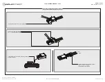
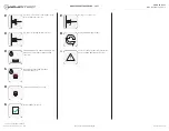
COMPONENT LOCATOR - 1 OF 1
INTERIOR VIEW
DRIVER SIDE VIEW
PASSENGER SIDE VIEW
www.idatastart.com
Automotive Data Solutions Inc. © 2021
AKX-IDS(RS)-BZ1A-[CMBMXA0]-EN
PAGE 6 OF 23
• 20211012
DOC.: #77310
Page 1: ...fit commercial loss loss of economic opportunity and the like that may or may not have resulted from the use misuse improper installation or operation of its products ADS reserves itself the right to...
Page 2: ...MERCEDES BENZ GL Class PTS AT 07 12 2 GL Class STD key AT 07 12 1 GL Class Diesel PTS AT 07 12 2 GL Class Diesel STD key AT 07 12 1 ML Class PTS AT 06 11 2 ML Class STD key AT 06 11 1 ML Class Diesel...
Page 3: ...EXTRA CONNECTOR HOUSING 10 PIN WHITE CONNECTOR 12 PIN BLACK CONNECTOR PROGRAMMING BUTTON LED 1 LED 2 RED BLUE BLACK BLACK RF PORT WEBLINK PORT BLACK BLUE BLACK BLACK BLACK USB BLUE TELEMATIC PORT WHIT...
Page 4: ...ACCESSORIES 1 OF 1 RF KIT RF KIT Visit our website to see if this accessory is included with your product ANTENNA FLASH RF DECODER BEFORE INSTALLATION RF DECODER BLUE CABLE BLACK CABLE NC RED NC BLAC...
Page 5: ...embly Procedure videos Module Connection Procedures videos Module Programming Procedures videos To access the videos simply log in your Weblink user account and click on Install videos under the Suppo...
Page 6: ...8 856 780 CA 2759622 A B COMPONENT LOCATOR 1 OF 1 INTERIOR VIEW DRIVER SIDE VIEW PASSENGER SIDE VIEW www idatastart com Automotive Data Solutions Inc 2021 AKX IDS RS BZ1A CMBMXA0 EN PAGE 6 OF 23 20211...
Page 7: ...ed before performing any system tests Failure to comply will result in vehicle displaying error messages An OEM scantool will be required to clear the error messages START the vehicle Verify all vehic...
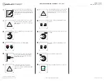
Page 8: ...10 PIN WHITE 10 PIN 1 TO CONNECT THE MODULE FOLLOW STEPS 1 TO 4 2 TO DISCONNECT THE MODULE FOLLOW STEPS 4 TO 1 IF NOT EQUIPPED WITH AN OEM HOOD SWITCH INSTALL AN AFTERMARKET HOOD SWITCH CONNECT TO MOD...
Page 9: ...enger side A ML Class PTS AT 06 11 CanH Black 02 pin 01 Brown Red DATA Passenger kick panel B CanL Black 02 pin 02 Brown DATA Passenger kick panel B ML Class Diesel PTS AT 06 11 CanH Black 02 pin 01 B...
Page 10: ...ITCH CONNECT TO MODULE RELAY B VEHICLE HARNESS A VEHICLE HARNESS B A STEP 2 WARNING CONNECT TO MODULE CONNECT IF REQUIRED HOOD SWITCH STEP 3 STEP 4 01 PINK RED CANH 02 PINK BLACK CANL CAN JUNCTION CON...
Page 11: ...ANISM 3 INSERT EMPTY HOUSING IN CAN JUNCTION CONNECTOR TO AVOID LOSING IT 4 INSERT CAN WIRES IN PROVIDED HOUSING CONNECT IT WITH C1 HARNESS AS SHOWN IN WIRING DIAGRAM INSTRUCTIONS TO CHANGE THE HOUSIN...
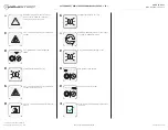
Page 12: ...solid GREEN then will turn OFF WARNING If LED 1 ashes RED GREEN turn ignition to OFF position The vehicle is PTS Follow appropriate PTS sections START vehicle for 15 seconds LED 1 will turn solid RED...
Page 13: ...LED 1 will ash RED GREEN Disconnect the first connector of the CAN junction connector whose CanH and CanL wires match the colors listed in the WIRE CHART Wait 5 seconds If the parking lights ash the...
Page 14: ...tion Complete next step within 7 seconds Cycle ignition ON five times 5x OFF ON rapidly Parking Light will ash once 1x Wait Parking Light will ash twice 2x pause for 1 5 second then will ash once 1x t...
Page 15: ...seconds Cycle ignition ON five times 5x OFF ON rapidly Parking Light will ash once 1x Time restriction Complete next step within 5 seconds from previous step Press once 1x on LOCK button of aftermark...
Page 16: ...icates LED 1 will ash RED an equal amount of times continuously TO ACCESS THE SETTINGS Press and hold programming button until LED 1 turns solid GREEN LED 1 will ash GREEN as many times as the current...
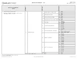
Page 17: ...01 OFF 02 ON 05 TAKEOVER 01 ENABLE 02 DISABLE 06 SECURE TAKEOVER DELAY 01 45 SEC 02 90 SEC 03 03 MIN 04 04 MIN 07 FACTORY KEYLESS RS SEQUENCE 01 DISABLE 02 N A 03 LOCK UNLOCK LOCK 04 LOCK LOCK LOCK 0...
Page 18: ...SHUTDOWN ERROR CODES NOTES Y NUMBER OF PARKING LIGHT FLASHES DIAGNOSTIC I WARNING The following applies only when the parking lights are connected and supported by the system 01 Engine tach signal is...
Page 19: ...incorrectly programmed Solid RED Module incorrectly programmed Flashing GREEN Module correctly programmed and operational Solid GREEN then OFF Reset in progress OFF Invalid ground when running status...
Page 20: ...s programming button while connecting the BLACK 20 PIN connector Wait LED 1 will ash RED RELEASE programming button LED 1 will turn RED for 2 seconds Module RESET completed Reconnect all connectors R...
Page 21: ...ush button start operation Time restriction Complete steps 2 to 6 within 45 seconds Unlock driver door Open driver door and enter vehicle Close driver door Push start button once 1x to ON position OR...
Page 22: ...e hood YES Leave hood open and go to step 9 NO Put the mandatory orange warning sticker Sticker 1 leave hood open and go to step 9 09 Close all doors 10 Press LOCK button three times 3x rapidly on the...
Page 23: ...r door QUESTION 8 Does the vehicle shut down YES The module does NOT detect the unlock signal from the vehicle communication network Call technical support NO Go to step 22 22 Enter vehicle QUESTION 9...