background image

814 OPERATOR’S MANUAL 


SYMBOLS & LABELS  


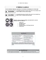
THE FOLLOWING SYMBOLS & LABELS MAY BE FOUND IN THIS MANUAL OR ON THE SAW 


A potentially hazardous situation exists which, if not avoided, could 
result in death or serious personal injury. 


A potentially hazardous situation exists which, if not avoided, may 
result in minor or moderate personal injury. 


WARNING 


CAUTION 


Read the operator’s manual carefully and understand the contents  
before you use this equipment. 


Always use: 


Protective helmet 


Ear protection 


Protective glasses or full face protection   


Safety shoes 

Summary of Contents for 814

Page 1: ...Copyright ICS 2003 P N 74595 12 03 814 Concrete Cutting Chainsaw OPERATOR S MANUAL ICS Blount Inc 4909 SE International Way Portland OR 97222 www icsbestway com...

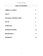
Page 2: ...814 OPERATOR S MANUAL 2 TABLE OF CONTENTS SYMBOLS LABELS 3 SAFETY 4 TECHNICAL SPECIFICATIONS 6 SET UP 7 OPERATION 9 TROUBLESHOOTING 12 MAINTENANCE 13 REFERENCE 14...

Page 3: ...could result in death or serious personal injury A potentially hazardous situation exists which if not avoided may result in minor or moderate personal injury WARNING CAUTION Read the operator s manu...

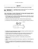
Page 4: ...ydraulic flow or 2500 psi 140 bar hydraulic pressure DO NOT install or run the chain backwards The bumper should lead the segment into the cut DO NOT run the saw motor backwards The chain should trave...

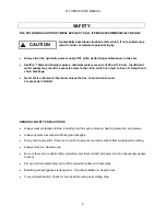
Page 5: ...mond chaninsaw unless the bar chain and side cover are properly installed GENERAL SAFETY PRECAUTIONS Always wear protective clothes including hard hat eye protection hearing protection and gloves Alwa...

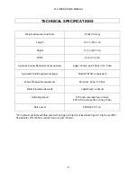
Page 6: ...72 5 bar Hydraulic Fluid Requirements type Mobil DTE13M or equivalent Water Pressure Requirements Minimum 20 psi 1 5 bar Water Flow Requirements 2 gpm 8 lpm minimum Operating Speed 5 700 rpm average f...

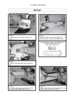
Page 7: ...comes into contact with the drive STEP 4 Mount the chain on the bar starting at the drive sprocket continue over the bar nose STEP 5 Make sure all the drive links are inside the bar groove then pre te...

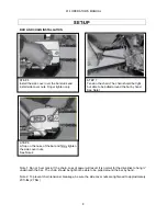
Page 8: ...round the bar by hand Note 2 To prevent chain tensioner breakage be sure the side cover nuts are tightened to approximately 20 ft lbs 27 Nm STEP 6 Install the side cover over the bar studs and install...

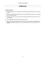
Page 9: ...ly to the Saw Maximum Flow 8 gpm 30 lpm Maximum Hydraulic Pressure 2 500 psi 172 bar Proper Hydraulic Motor Rotation Some power packs have reversible flow Or the quick disconnects may have been revers...

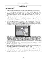
Page 10: ...d simply engage the point of the Wallwalker into the cut and push straight in The Wallwalker will force the saw to feed down Apply an upward force on the trigger handle to keep the Wallwalker engaged...

Page 11: ...ter pressure spraying water into all three openings 3 Remove bar and chain Flush out chain tensioner assembly location with high water pressure and lube with grease 4 Clean all hydraulic flush face fi...

Page 12: ...ck to expose the diamonds PREMATURE CHAIN STRECH Not enough water pressure The minimum water pressure required is 20 psi 1 4 bar Insufficient water supply may result in excessive wear to the chain whi...

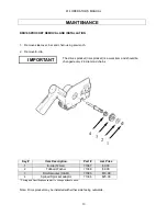
Page 13: ...art List Price 1 E clip 12mm 71387 3 00 2 Tabbed Washer 71388 6 00 3 Rim Sprocket 3 8 8t 71385 10 00 4 Splined Sprocket adaptor 71386 25 00 Pricing and Specifications subject to change without notice...

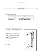
Page 14: ...10 20 seconds through each piece INCH FOOT DEFINITION An in ft is a measure of how much material is to be cut An in ft is defined as depth in inches times length in feet Example How many in ft are in...

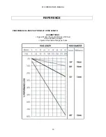
Page 15: ...814 OPERATOR S MANUAL 15 REFERENCE PERFORMANCE LOSS VS HYDRAULIC HOSE LENGTH ASSUMPTIONS 8 gpm 30 lpm flow and 2 500 psi 172 bar Zero elevation change 2 pairs of flush face fittings per hose...

Reviews: