ICS 680ES, Service Manual
The ICS 680ES Operator's Manual is available for free download on our website. This comprehensive manual provides detailed instructions and essential information to ensure safe and efficient operation of the ICS 680ES product. Access the manual now at manualshive.com and optimize your experience with this top-notch tool.
Share
Download


Reviews:
No comments
Related manuals for 680ES
814
Brand: ICS Pages: 15

G5000
Brand: Zenoah Pages: 15
FORMULA 60
Brand: Gardena Pages: 15
G5200
Brand: Zenoah Pages: 17
UC3050A
Brand: Makita Pages: 13
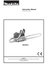
DCS 9010
Brand: Makita Pages: 28
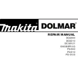
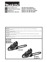
DCS460
Brand: Makita Pages: 32
DCS3500
Brand: Makita Pages: 32
EA6100P
Brand: Makita Pages: 30
DCS460
Brand: Makita Pages: 32
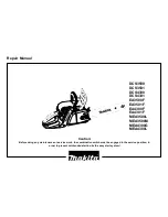
DCS34
Brand: Makita Pages: 28
EA5600F
Brand: Makita Pages: 36
EA3500S
Brand: Makita Pages: 40
EA3600F
Brand: Makita Pages: 104
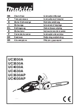
UC3530A
Brand: Makita Pages: 136
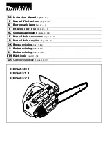
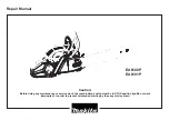
DCS230T
Brand: Makita Pages: 120
5014B
Brand: Makita Pages: 2
EA3200S
Brand: Makita Pages: 15


