Operating Instructions
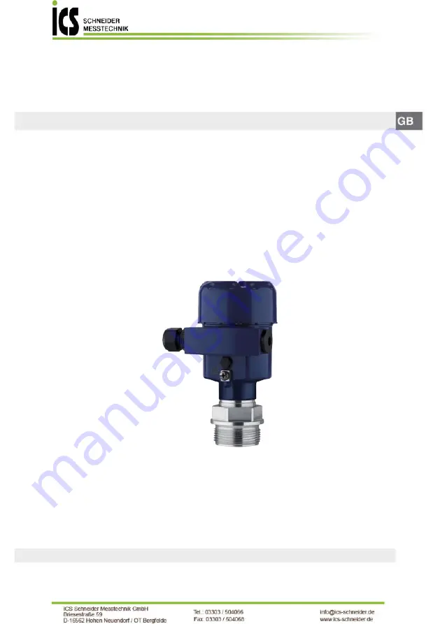
Process pressure transmitter CPT-2x
4 … 20 mACeramic measuring cell
Page 1: ...Operating Instructions Process pressure transmitter CPT 2x Process pressure transmitter CPT 2x 4 20 mA Ceramic measuring cell...
Page 2: ...ation and pressure compensation 16 4 4 Process pressure measurement 18 4 5 Level measurement 20 4 6 External housing 21 5 Connecting to power supply 22 5 1 Preparing the connection 22 5 2 Connecting 2...
Page 3: ...ation of the total deviation 64 9 3 Calculation of the total deviation Practical example 64 9 4 Dimensions 67 9 5 Trademark 75 Safety instructions for Ex areas Take note of the Ex specific safety inst...
Page 4: ...ols used Information note tip This symbol indicates helpful additional infor mation and tips for successful work Note This symbol indicates notes to prevent failures malfunctions damage to devices or...
Page 5: ...instructions This is a state of the art instrument complying with all prevailing regulations and directives The instrument must only be operated in a technically flawless and reliable condition The o...
Page 6: ...ndations NE 21 Electromagnetic compatibility of equipment NE 43 Signal level for fault information from measuring transduc ers NE 53 Compatibility of field devices and display adjustment components NE...
Page 7: ...certificates Information Optional instrument features are also described in this operating instructions manual The respective scope of delivery results from the order specification This operating ins...
Page 8: ...ion 3 2 Principle of operation CPT 2x is suitable for applications in virtually all industries It is used for the measurement of the following pressure types Gauge pressure Absolute pressure Vacuum Me...
Page 9: ...he ceramic base of the 17 5 mm measuring cell detects the actual process temperature The temperature value is output via the master sensor Even extreme jumps in process temperature are immediately de...
Page 10: ...c measuring cell into the process fitting and the different seal concepts The recessed installation is particularly suitable for applications with gases vapours and clear liquids The measuring cell se...
Page 11: ...le M30 x 1 5 1 Measuring cell 2 Seal for the measuring cell 3 Seal for the process fitting 4 Process fitting 5 Diaphragm The front flush installation is particularly suitable for applications with vis...
Page 12: ...e in the process fitting is used for leakage detection 1 6 2 3 4 5 Fig 9 Hygienic installation of the measuring cell acc to 3 A example Clamp connection 1 Measuring cell 2 Seal for the measuring cell...
Page 13: ...rt packaging Nonobservance of these instructions can cause damage to the device The delivery must be checked for completeness and possible transit damage immediately at receipt Ascertained transit dam...
Page 14: ...moisture ingress through the following measures Use a suitable connection cable see chapter Connecting to power supply Tighten the cable gland or plug connector Lead the connection cable downward in f...
Page 15: ...ice a test pressure may only exceed the specified MWP briefly by 1 5 times at reference tempera ture The pressure stage of the process fitting as well as the overload resistance of the measuring cell...
Page 16: ...uld be avoided Danger of explosion 4 3 Ventilation and pressure compensation The filter element in the electronics housing has the following func tions Ventilation of the electronics housing Atmospher...
Page 17: ...ug is installed instead of the filter element Instruments in protection IP66 IP68 1 bar ventilation via capillar ies in non detachable cable Instruments with absolute pressure Turn the metal ring in s...
Page 18: ...ly is completely en capsulated An absolute pressure measuring cell is used so that no ventilation is required With relative pressure measuring ranges the ambient pressure is detected and compensated b...
Page 19: ...m Connect via a siphon Do not insulate the siphon Fill the siphon with water before setup 1 4 3 2 1 2 3 4 Fig 16 Measurement setup for the process pressure measurement of gases in pipelines 1 CPT 2x 2...
Page 20: ...g 17 Measurement setup for the process pressure measurement of liquids in pipelines 1 CPT 2x 2 Blocking valve 3 Pipeline 4 5 Level measurement Keep the following in mind when setting up the measuring...
Page 21: ...cess pressure transmitter CPT 2x 4 6 External housing 1 2 3 4 5 Fig 19 Configuration process module external housing 1 Pipeline 2 Process module 3 Connection cable process assembly External housing 4...
Page 22: ...or 22 mA in case of fault Influence of additional instruments in the circuit see load values in chapter Technical data The instrument is connected with standard two wire cable without shielding If ele...
Page 23: ...otection caps as transport protection Note Prior to setup you have to replace these protective caps with ap proved cable glands or close the openings with suitable blind plugs On plastic housings the...
Page 24: ...om above with a small screwdriver the terminal opening is then free When the screwdriver is released the terminal closes again 7 Check the hold of the wires in the terminals by lightly pulling on them...
Page 25: ...oltage supply signal output 2 For display and adjustment module or interface adapter 3 Ground terminal for connection of the cable screening 5 4 Housing IP66 IP68 1 bar 1 2 Fig 22 Wire assignment in p...
Page 26: ...2x in IP68 version 25 bar with axial cable outlet external housing 1 Transmitter 2 Connection cable 3 External housing 1 2 3 5 1 2 6 7 8 4 20mA Fig 24 Electronics and connection compartment 1 Electro...
Page 27: ...amber housing 1 Voltage supply signal output 2 For display and adjustment module or interface adapter 3 Ground terminal for connection of the cable screening 5 6 Switch on phase After connecting the i...
Page 28: ...supply WIKA Operating Instructions Process pressure transmitter CPT 2x Then the actual measured value is output to the signal cable The value takes into account settings that have already been carried...
Page 29: ...adjustment module on the electronics in the desired position and turn it to the right until it snaps in 3 Screw housing lid with inspection window tightly back on Disassembly is carried out in reverse...
Page 30: ...1 s the value or position changes continuously When the OK and ESC keys are pressed simultaneously for more than 5 s the display returns to the main menu The menu language is then switched over to En...
Page 31: ...he individual steps with the key After the last step Quick setup terminated successfully is displayed briefly The return to the measured value indication is carried out through the or ESC keys or auto...
Page 32: ...rement loop name or the tank or product designation In digital systems and in the documentation of larger plants a singular desig nation must be entered for exact identification of individual measurin...
Page 33: ...the measured value Position correction compensates this offset In the process the actual measured value is taken over automatically With relative pressure measuring cells a manual offset can also be c...
Page 34: ...hese settings the real filling height is then calculated The actual product level during this adjustment is not important because the min max adjustment is always carried out without changing the prod...
Page 35: ...n be aborted with ESC or the displayed limit value can be accepted with OK Proceed as follows 1 Select with the menu item Span adjustment and confirm with OK 2 Edit the mbar value with OK and set the...
Page 36: ...nd save with OK The cursor jumps now to the pressure value 4 Enter the pressure value for the full vessel e g 900 mbar cor responding to the percentage value 5 Save settings with OK The max adjustment...
Page 37: ...the filling height This must be considered by the user especially when setting the switching point on the limit signal transmitter In the menu item Current output mode you determine the output charac...
Page 38: ...em enables the setting of the requested national lan guage The following languages are available German English French Spanish Russian Italian Dutch Portuguese Japanese Chinese Polish Czech Turkish In...
Page 39: ...h description rea son as well as rectification in chapter Asset Management The respective min and max measured values are saved in the sensor The two values are displayed in menu item Peak values pres...
Page 40: ...r are reset The following reset functions are available Delivery status Restores the parameter settings at the time of shipment from the factory incl the order specific settings Any user defined linea...
Page 41: ...u item Default value Menu language Selected language Displayed value 1 Current output in Displayed value 2 Ceramic measuring cell Measuring cell temperature in C Metallic measuring cell Electronics te...
Page 42: ...u Additional adjustments the items Reset Date Time The user programmable linearization curve The copied data are permanently saved in an EEPROM memory in the display and adjustment module and remain t...
Page 43: ...asured variable then e g 0 C refers to 4 mA and 100 C to 20 mA In this menu item you gain access to the protected area where you can enter special parameters In exceptional cases individual parameters...
Page 44: ...cess fitting seal measuring range electronics housing and others are displayed 6 6 Saving the parameterisation data We recommended writing down the adjustment data e g in this op erating instructions...
Page 45: ...ethods corresponding to the housing protec tion rating 7 2 Cleaning hygienic connection with compression nut The hygienic connection with compression nut can be disassembled and the diaphragm cleaned...
Page 46: ...ing for example illogical value pairs Check linearisation table Delete table Create new F036 no operable sensor software Failed or interrupted software update Repeat software update Check electronics...
Page 47: ...ctification S600 Impermissible electronics temperature Temperature of the electronics in the non specified range Check ambient temperature Insulate electronics Use instrument with higher tempera ture...
Page 48: ...and faults rectified Connect a multimeter in the suitable measuring range according to the wiring plan The following table describes possible errors in the current signal and helps to eliminate them E...
Page 49: ...ly from the process module 1 2 3 6 4 5 Fig 31 CPT 2x in IP68 version 25 bar and lateral cable outlet external housing 1 Process module 2 Plug connector 3 Fixing screw 4 Cable assembly 5 Connection cab...
Page 50: ...stics and servicing WIKA Operating Instructions Process pressure transmitter CPT 2x Clean the instrument and pack it damage proof Attach the completed form and possibly also a safety data sheet to the...
Page 51: ...cled by spe cialised recycling companies We use recyclable materials and have designed the electronics to be easily separable WEEE directive The instrument does not fall in the scope of the EU WEEE di...
Page 52: ...FKM VP2 A A P 70 16 EPDM A P 70 10 02 FFKM Kalrez 6375 Perlast G75S Perlast G75B Hygienic fitting with compression nut form seal FKM ET 6067 EPDM EPDM 7076 FFKM Chem raz 535 FEPM Fluoraz SD890 Seal f...
Page 53: ...1 5 50 Nm 36 88 lbf ft G1 for PASVE 100 Nm 73 76 lbf ft G1 200 Nm 147 5 lbf ft Max torque for screws PMC 1 PMC 1 2 Nm 1 475 lbf ft PMC 1 5 Nm 3 688 lbf ft Max torque for NPT cable glands and Conduit t...
Page 54: ...1 bar 100 kPa 1 1 5 bar 100 150 kPa 40 bar 4000 kPa 1 bar 100 kPa 1 10 bar 100 1000 kPa 90 bar 9000 kPa 1 bar 100 kPa 1 25 bar 100 2500 kPa 125 bar 12500 kPa 1 bar 100 kPa 1 60 bar 100 6000 kPa 200 b...
Page 55: ...4 51 psig 14 5 0 psig 525 psig 14 51 psig 14 5 20 psig 600 psig 14 51 psig 14 5 75 psig 975 psig 14 51 psig 14 5 150 psig 1350 psig 14 51 psig 14 5 300 psig 1900 psig 14 51 psig 14 5 900 psig 2900 psi...
Page 56: ...Output signal 4 20 mA passive Connection technology Two wire Range of the output signal 3 8 20 5 mA default setting Signal resolution 0 3 A Fault signal current output adjustable 3 6 mA 21 mA last me...
Page 57: ...A Deviation according to IEC 60770 Applies to the digital signal output HART Profibus PA Foundation Fieldbus as well as to the ana logue current output 4 20 mA and refers to the set span Turn down TD...
Page 58: ...asuring range 0 1 barabs 0 2 0 05 0 1 with meas uring range 25 mbar Factor FMZ 1 2 3 Additional factor through Turn Down The additional factor FTD through Turn down is calculated according to the foll...
Page 59: ...28 mm Measuring cell 17 5 mm Measuring ranges from 0 0 1 bar 0 10 kPa Measuring range 0 0 025 bar 0 2 5 kPa All process fittings8 Process fitting G ISO 228 1 One year 0 05 x TD 0 1 x TD 0 1 x TD 0 25...
Page 60: ...7056 40 130 C 40 266 F E70Q 40 150 C 40 302 F Fluoraz SD890 5 130 C 22 266 F FFKM Kalrez 6375 20 130 C 4 266 F 20 150 C 4 302 F Perlast G75S 15 130 C 4 266 F 15 150 C 5 302 F Perlast G75B 15 130 C 4...
Page 61: ...see specification process pressure on the type label Mechanical stress11 Vibration resistance 4 g at 5 200 Hz according to EN 60068 2 6 vibration with resonance Shock resistance 50 g 2 3 ms according...
Page 62: ...AWG 20 Wire resistance R 0 037 m 0 012 ft Electromechanical data version IP68 25 bar Connection cable transmitter external housing mechanical data Configuration Wires strain relief breather capillari...
Page 63: ...Hz for UN 24 V DC 18 V UB 35 V 1 0 Veff 16 400 Hz Load resistor Calculation UB Umin 0 022 A Example with UB 24 V DC 24 V 9 6 V 0 022 A 655 Potential connections and electrical separating measures in...
Page 64: ...ror FT is shown in a graphic Depending on the measuring cell version and Turn down this value must be multiplied with the additional factors FMZ and FTD FT x FMZ x FTD Also these values are specified...
Page 65: ...ng cell for above example FMZ 3 Turn down TD 1 1 TD 2 5 1 TD 5 1 TD 10 1 TD 20 1 Factor FTD 1 1 75 3 5 5 10 5 Tab 22 Determination of the additional factor turn down for the above example FTD 1 75 FT...
Page 66: ...long term stability from the table consideration for one year Fstab 0 05 x TD 4 Calculation of the total deviation 4 20 mA signal 1 step Basic deviation Fperf Fperf FT 2 FKl 2 Fa 2 FT 0 79 FKl 0 2 Fa...
Page 67: ...mm 4 61 M20x1 5 NPT 59 mm 2 32 80 mm 3 15 112 mm 4 41 M20x1 5 NPT 84 mm 3 31 1 2 4 3 5 104 mm 4 1 M20x1 5 NPT 59 mm 2 3 80 mm 3 15 Fig 38 Housing versions in protection IP66 IP67 and IP66 IP68 0 2 ba...
Page 68: ...5 108 mm 4 25 41 6 mm 1 64 66 mm 2 60 59 mm 2 32 110 mm x 90 mm 4 33 x 3 54 110 mm x 90 mm 4 33 x 3 54 51 mm 2 01 41 6 mm 1 64 90 mm 3 54 R 3 5 mm 0 14 3mm 0 12 70 mm 2 76 8 mm 0 32 93 mm 3 66 110 mm...
Page 69: ...3 mm 0 12 20 mm 0 79 3 mm 0 12 20 mm 0 79 2 mm 0 08 3 mm 0 12 6 mm 0 24 17 5 mm 0 69 17 5 mm 0 69 G NPT M20x1 5 15 mm 0 59 25 mm 0 98 75 mm 2 95 5 mm 0 20 3 mm 0 12 6 mm 0 24 25 mm 0 98 75 mm 2 95 NPT...
Page 70: ...97 55 mm 2 17 22 mm 0 87 25 mm 0 87 55 mm 2 17 60 mm 2 36 1 NPT 50 mm 1 97 22 mm 0 87 55 mm 2 17 SW 46 mm 1 81 SW 55 mm 2 17 SW 46 mm 1 81 1 2 3 6 5 4 Fig 41 CPT 2x threaded fitting front flush 1 G IS...
Page 71: ...mm 4 13 1 2 3 4 6 5 7 Fig 42 CPT 2x hygienic fitting 1 Clamp 2 2 Hygienic connection with compression nut F40 3 DRD 4 Tuchenhagen Varivent DN 32 5 Slotted nut DN 40 according to DIN 11851 6 Slotted n...
Page 72: ...152 4 190 5 23 9 152 4 8x 19 1 127 3 2 DN inch PN D k b 40 40 50 40 d2 d4 f 80 40 3 62 0 13 4x 0 75 4 75 0 75 6 3 2 150 lbs 150 lbs 150 lbs 150 lbs 1 97 1 97 2 01 2 01 H 2 01 H 50 50 51 51 51 1 2 1 2...
Page 73: ...0 mm 1 18 106 mm 4 17 G1 SW 36 mm 1 42 24 7 mm 0 97 M8 Fig 44 CPT 2x extension fitting 1 M30 x 1 5 DIN 13 completely front flush 2 M30 x 1 5 DIN 13 for headbox 3 M44 x 1 25 DIN 13 pressure screw Alumi...
Page 74: ...70 mm 2 76 45 mm 1 77 75 mm 2 95 65 mm 2 56 41 mm 1 63 7 16 20 UNF 1 4 18 NPT 40 mm 1 57 Fig 45 CPT 2x connection acc to IEC 61518 1 Oval flange adapter 2 Top flange For the version with temperature...
Page 75: ...75 9 Supplement WIKA Operating Instructions Process pressure transmitter CPT 2x 9 5 Trademark All the brands as well as trade and company names used are property of their lawful proprietor originator...
Page 76: ...ing 39 E Electronics and connection compartment single chamber housing 25 Electronics and connection compartment single chamber housing 27 Error codes 46 47 F Fault Rectification 48 Fault rectificatio...
Page 77: ...77 Notes WIKA Operating Instructions Process pressure transmitter CPT 2x...
Page 78: ...78 Notes WIKA Operating Instructions Process pressure transmitter CPT 2x...
Page 79: ...79 Notes WIKA Operating Instructions Process pressure transmitter CPT 2x...
Page 80: ...Printing date...