


119
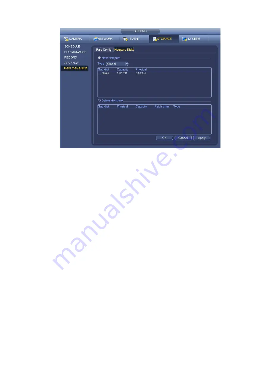
Figure 4-136
4.14 Basic Setups
Set NVR basic setup, device setup and other setups.
4.14.1
Device Setup
From Main menu->Setting->System->General, you can go to the general interface. See Figure 4-138.
Pack duration: Here is for you to specify record duration. The value ranges from 0 to 120 minutes.
Default value is 60 minutes.
Device ID: Please input a corresponding device name here.
Device No: When you are using one remote control (not included in the accessory bag) to control
several NVRs, you can give a name to each NVR for your management.
Language: System supports various languages: Chinese (simplified), Chinese (Traditional), English,
Italian, Japanese, French, Spanish (All languages listed here are optional. Slight difference maybe
found in various series.)
Video standard: There are two formats: NTSC and PAL.
HDD full: Here is for you to select working mode when hard disk is full. There are two options: stop
recording or rewrite. If current working HDD is overwritten or the current HDD is full whi le the next
HDD is no empty, then system stops recording, If the current HDD is full and then next HDD is not
empty, then system overwrites the previous files.
Pack duration: Here is for you to specify record duration. The value ranges from 1 to 120 minute s.
Default value is 60 minutes.
Realtime play: It is to set playback time you can view in the preview interface. The value ranges from
5 to 60 minutes.
Auto logout: Here is for you to set auto logout interval once login user remains inactive for a
specified time. Value ranges from 0 to 60 minutes.
Navigation bar: Check the box here, system displays the navigation bar on the interface.
Summary of Contents for NVR-7508K
Page 1: ...Network Video Recorder User s Manual V 2 0 0 ...
Page 8: ...vii 9 Appendix B Compatible Network Camera List 217 ...
Page 85: ...74 Figure 4 81 Figure 4 82 ...
Page 86: ...75 Figure 4 83 Figure 4 84 ...
Page 92: ...81 Figure 4 89 Figure 4 90 ...
Page 93: ...82 Figure 4 91 Figure 4 92 ...
Page 94: ...83 Figure 4 93 Figure 4 94 ...
Page 96: ...85 Figure 4 96 Figure 4 97 ...
Page 183: ...172 The motion detect interface is shown as in Figure 5 54 Figure 5 54 Figure 5 55 ...
Page 184: ...173 Figure 5 56 Figure 5 57 Figure 5 58 ...
Page 188: ...177 Figure 5 62 Figure 5 63 ...


