ICRealtime ICIP-3000CCD-W User Manual Download Page 8


Do not connect two power supplying sources to the device at the same time; it 
may result in device damage!


PoE 


Support Power over Ethernet (PoE). Conform to the IEEE802.3af standard. 


Connect the device to the switcher or the router that supports the PoE function to 
realize the network power supply. 


To guarantee proper performance, please make sure the power sourcing device 
can supply at least 10W power. 


Usually, do not use the PoE for the WIFI/3G device. 

Assistant 

Function 


Day/Night mode auto switch (

ICR switch.


Backlight compensation: screen auto split to realize backlight compensation to 
adjust the bright.  


Support system resource information and running status real-time display. Support 
log function. 


Support video watermark function to avoid vicious video modification. 


Support auto aperture.  


Support picture parameter setup such as electronic shutter and gain setup. 


Support dual-stream, ACF(Active frame control ) 

1.3


Specifications 

1.3.1  Performance  

Please refer to the following sheet for network camera performance specification. 
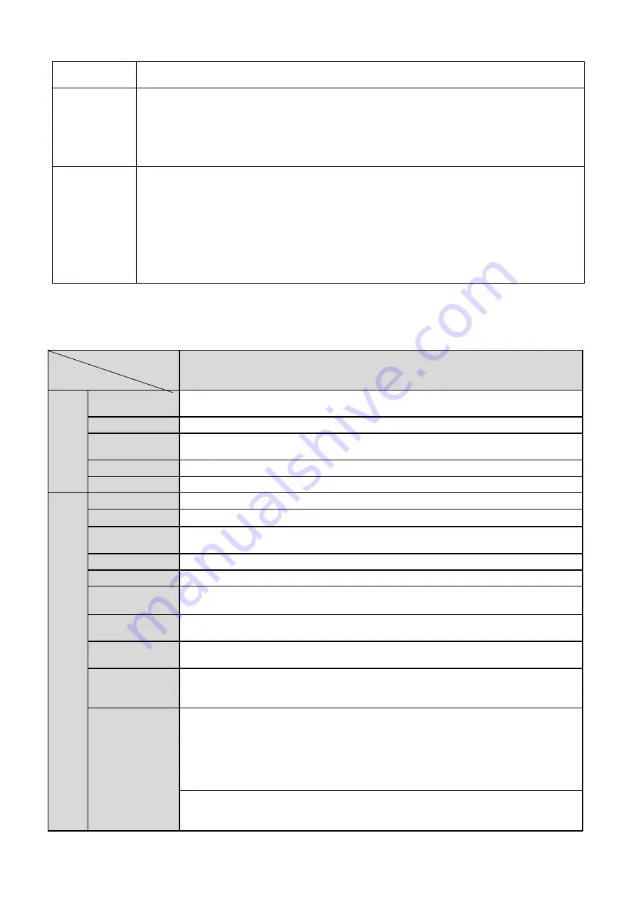
           Model 
 
Parameter 

ICIP 3000CCD-W 

S

yste


Main 
Processor  

TI Davinci high performance DSP 

OS 

Embedded LINUX 

System 
Resources 

Support  real-time  network,  local  record,  and  remote  operation  at  the  same 
time.  

User Interface 

Remote operation interface such as WEB, DSS, PSS 

System Status 

SD card status, bit stream statistics, log, and software version.  

V

ide
o Par

amet

er
 

Image Sensor  

1/2.8-inch CMOS 

Pixel 

2080(H)*1553(V) 

Day/Night 
Mode 

Support day/night mode switch and IR-CUT at the same time. 

Auto Aperture  

Optional 

Gain Control  

Fixed/Auto 

White Balance 

Manual/Auto 

 BLC 

Off/BLC/WDR  (1-100  adjustable)/HLC(anti-flicker  is  outdoor  and  is  valid  only 
when exposure mode is auto with range 1-100) 

Electronic 
Shutter 

Manual/Auto 
It ranges from 1/3 to 1/10000. 

Video 
Compression 
Standard 

H.264/ H.264H/H.264B/MJPEG 
Note: Some versions do not support H.264H. 

Video 

Frame 

Rate 

PAL:  
Main stream (2048*1536@18fps) 
Extra stream (704*576@18fps) 
Main stream (1920*1080@25fps) 
Extra stream (704*576@25fps) 

NTSC:  
Main stream (2048*1536@20fps) 
Extra stream (704*480@20fps) 

Summary of Contents for ICIP-3000CCD-W

Page 1: ...Megapixel Indoor Network Camera User s Manual Version 4 1 1...

Page 2: ...r network camera This user s manual is designed to be a reference tool for your system Please read the following safeguard and warnings carefully before you use this series product Please keep this us...

Page 3: ...power to the camera before completing installation Please install the proper power cut off device during the installation connection Always follow the instruction guide the manufacturer recommended 4...

Page 4: ...n you do not use the camera Dome enclosure is the optical component do not touch the enclosure when you are installing the device or clean the enclosure when you are doing maintenance work Please use...

Page 5: ...ectional talk 10 2 4 1 Device end to PC end 10 2 4 2 PC end to the Device end 10 2 5 Alarm Setup 10 2 5 1 Alarm Input and Output Connection 11 2 5 2 IR Light Connection 12 3 Installation 13 3 1 Lens I...

Page 6: ...ion 17 3 4 2 Remove 18 3 5 I O Port 19 4 Quick Configuration Tool 20 4 1 Overview 20 4 2 Operation 20 5 Web Operation 22 5 1 Network Connection 22 5 2 Login and Main Interface 22 6 FAQ 24 Appendix Tox...

Page 7: ...ction Support central server backup function in accordance with your configuration and setup in alarm or schedule setting Support record via Web and the recorded file are storage in the client end PC...

Page 8: ...tions 1 3 1 Performance Please refer to the following sheet for network camera performance specification Model Parameter ICIP 3000CCD W System Main Processor TI Davinci high performance DSP OS Embedde...

Page 9: ...ation event alarm device audio video storage image snapshot log email function and etc Camera Masking Activation event alarm device audio video storage image snapshot log email SMTP function and etc A...

Page 10: ...meter Power Support AC24V DC12V power and PoE Power Consumption 10W For WIFI and 3G device it is below 12W Working Temperature 20 60 Working Humidify 95 Dimensions 70 63 2 149 5 Weight 650g Installati...

Page 11: ...es IP camera real panel is shown as below See Figure 2 1 The rear panel with the network port The rear panel with the 100M fiber port Figure 2 1 Rear panel Note Picture in this chapter is for referenc...

Page 12: ...STATUS Indication Light Red light System boot up red light is on System upgrades red light flashes System resets red light flashes Green light Normal working status green light is on Display record s...

Page 13: ...open alarm output end C Alarm output public end C G GND Alarm input ground end A RS485 port RS485_A port control external PTZ B RS485_B port control external PTZ RX RS232 port RS232_RX RS232 receive e...

Page 14: ...AN Network port Ethernet port Connect to standard Ethernet cable Support PoE function OPT 100M fiber port 155M single fiber dual direction SFP fiber module Transmit 100M Ethernet data SD SD card port...

Page 15: ...ion GND Please make sure the device is securely earthed to prevent the thunderstorm strike 2 2 Side Panel Please refer to the following interface for side panel dimension information The unit is mm Se...

Page 16: ...the speaker or the pickup and then you can get the audio from the earphone or sound box at the pc end 2 4 2 PC end to the Device end Device Connection Connect the speaker or the MIC to the audio inpu...

Page 17: ...cording to the high low level type when an alarm occurs Step 4 Set the WEB alarm output The alarm output 01 is the alarm output port of the device rear panel as the NO port 2 5 1 Alarm Input and Outpu...

Page 18: ...Note Device shall have external port for IR function Log in Web select Setup Camera Day Night and select sensor input If it is not available then you do need to set it Please refer to the following f...

Page 19: ...installation position of the C CS adapter Turn clockwise to fix the lens Use slotted screwdriver to fasten the screw near the focusing ring and then turn counter clockwise to move the focusing ring o...

Page 20: ...e steps listed below to remove lens The interface is shown as in Figure 3 3 Turn the lens counter clockwise and then remove it from the camera Unplug the auto lens cable socket from the auto lens conn...

Page 21: ...ap screw firmly to secure the SD card protection cap in the camera Figure 3 4 SD card installation 1 Figure 3 5 SD card installation 2 3 2 2 Remove Please follow the steps listed below to remove SD ca...

Page 22: ...the proper installation position Put the 3G card protection cap back Use the screwdriver to fix the 3G card protection cap screw firmly to secure the 3G card protection cap Figure 3 7 3G card installa...

Page 23: ...rear panel See Figure 3 10 Please turn according to the direction in the following figure until antenna is secure firmly See Figure 3 11 Figure 3 10 3G Wifi antenna installation 1 Figure 3 11 3G Wifi...

Page 24: ...thread end and then turn according to the following figure See Figure 3 13 Now you can see the antenna is away from the thread See Figure 3 14 Figure 3 13 Remove 3G Wifi antenna 1 Figure 3 14 Remove...

Page 25: ...wdriver to press the corresponding button of cable groove Insert the cable into the groove and then release the screwdriver Remove Cable Please follow the steps listed below to remove the cable Use th...

Page 26: ...ion Double click the ConfigTools exe icon you can see an interface is shown as in Figure 4 1 In the device list interface you can view device IP address port number subnet mask default gateway MAC add...

Page 27: ...user name password and port Please modify the corresponding information to login Please note the port information here shall be identical with the port value you set in TCP port in Web Network interfa...

Page 28: ...the PC and the network camera respectively Network camera default IP address is 192 168 1 108 Subnet mask is 255 255 255 0 Gateway is 192 168 1 1 Use order ping network camera address to check connect...

Page 29: ...gin After you successfully logged in please install WEB plug in unit Please refer to the Web Operation Manual included in the resource CD for detailed operation instruction See Figure 5 3 Figure 5 3 W...

Page 30: ...e schedule record file It may damage the SD card duration I can not use the disk as the storage media When disk information is shown as hibernation or capacity is 0 please format it first Via Web I ca...

Page 31: ...toxic or hazardous substance or elements contained in products will not leak or mutate so that the use of these substances or elements will not result in any severe environmental pollution any bodily...

Reviews: