

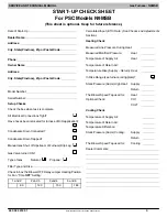


SERVICE AND TECHNICAL SUPPORT MANUAL
Gas Furnace: N9MSB
Specifications subject to change without notice.
6
440 04 4412 01
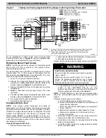
4. Turn on furnace power supply.
5. Turn gas supply manual shutoff valve to ON position.
6. Turn furnace gas valve switch to ON position.
7. Jumper R and W thermostat connections at the furnace
control board.
8. When main burners ignite, confirm inlet gas pressure is
between 4.5 in. w.c. (1125 Pa) and 13.6 in. w.c. (3388
Pa).
9. Remove jumper across thermostat connections to
terminate call for heat. Wait until the blower off delay is
completed.
10. Turn furnace gas valve electric switch to OFF position.
11. Turn gas supply manual shutoff valve to OFF position.
12. Turn off furnace power supply.
13. Remove manometer from the inlet pressure tap of the
gas valve.
FIRE HAZARD
Failure to follow this warning could result in personal injury,
death, and/or property damage.
Re
−
install manifold pressure tap plug in gas valve to
prevent gas leak.
!
WARNING
14. Apply pipe dope sparingly to end of inlet gas pipe plug
and re
−
install in the gas valve.
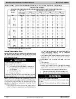
Adjust Manifold Pressure
1. Adjust manifold pressure to obtain proper gas input rate.
(See
)
a. Turn gas valve ON/OFF switch to OFF.
b. Remove manifold pressure tap plug from gas valve.
c. Connect a water column manometer or similar device
to manifold pressure tap.
d. Turn gas valve ON/OFF switch to ON.
e. Manually close blower door switch.
f. Jumper R and W thermostat connections on control
to start furnace. (See
)
g. Remove regulator adjustment cap from gas valve
pressure regulator (See
) and turn adjusting
screw (3/16 or smaller flat
−
tipped screwdriver)
counterclockwise (out) to decrease input rate or
clockwise (in) to increase input rate.
NOTICE
DO NOT set low
−
heat manifold pressure less than 2.8
−
in. w.c.
(697 Pa) or more than 3.8
−
in. w.c. (947 Pa) for natural gas. If
required manifold pressure is outside this range, change main
burner orifices.
h. When correct input is obtained, replace cap that
conceal gas valve regulator adjustment screw. Main
burner flame should be clear blue, almost transparent
)
i. Remove jumper R to W.
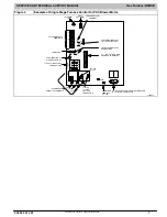
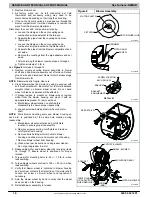
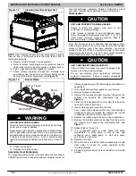
Figure 3
Redundant Automatic Gas Valve
(Single Stage)
ON/OFF Switch
Regulator Seal Cap
Regulator Adjustment
Regulator Seal Cap under Cap
1/2” NPT Outlet
1/8” NPT Manifold
Pressure Tap
1/8” NPT Inlet
Pressure Tap
1/2” NPT Inlet
A11153
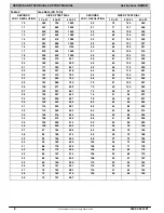
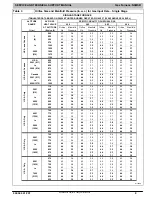
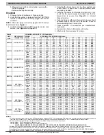
2. Verify natural gas input rate by clocking meter.
NOTE
: Contact your HVAC distributor or gas supplier for metric
gas meter Tables, if required.
a. Turn off all other gas appliances and pilots served by
the meter.
b. Jumper R to W.
c. Run furnace for 3 minutes.
d. Measure time (in sec) for gas meter to complete 1
revolution and note reading. The 2 or 5 cubic feet dial
provides a more accurate measurement of gas flow.
e. Refer to
f. Multiply gas rate cu ft./hr by heating value (Btuh/cu
ft.) to obtain input. If clocked rate does not match
required input from Step 1, increase manifold
pressure to increase input or decrease manifold
pressure to decrease input. Repeat steps b through e
until correct input is achieved. Re
−
install regulator
seal cap on gas valve.
g. If clocked rate does not match required input from
Step 1, increase manifold pressure to increase input
or decrease manifold pressure to decrease input.
Repeat steps b through e of Step 1 until correct heat
input is achieved. Re--install regulator seal cap on
gas valve.
3.
Restore furnace to normal operating condition.
a. Turn gas valve ON/OFF switch to OFF.
b. Remove water column manometer or similar device
from manifold pressure tap.
c. Replace manifold pressure tap plug to gas valve.
d. Turn gas valve ON/OFF switch to ON.
e. Check for gas leaks and verify furnace operation
FIRE HAZARD
Failure to follow this warning could result in personal injury,
death, and/or property damage.
Reinstall manifold pressure tap plug in gas valve to prevent
gas leak.
!
WARNING


