


SERVICE AND TECHNICAL SUPPORT MANUAL
Gas Furnace: N9MSB
Specifications subject to change without notice.
24
440 04 4412 01
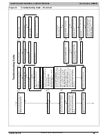
Figure 16 (CONT.) Troubleshooting Guide
−
Flow Chart
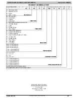
1
+ 2
BL
O
W
ER ON AF
T
E
R PO
W
E
R UP
–
(11
5
V
OR
24V
)
–
No
rm
al o
p
e
rati
o
n.
Blower
r
u
ns f
o
r 9
0
se
c
o
n
d
s, if
u
n
it is
po
w
e
re
d u
p
duri
ng
a c
a
ll f
o
r
hea
t (R
-
W
/W
1
closed)
or
whe
n (
R
-W
/W
1 opens
)
d
u
ri
n
g
t
h
e b
low
er
on
-d
e
la
y
pe
ri
od
.
6 + 1
IGN
IT
IO
N
LOCK
OUT
–
S
y
st
e
m
fa
iled
to
ignite
g
a
s a
n
d
pr
ove
flam
e i
n
4
attem
p
ts. C
o
n
trol
w
ill
a
u
to
-r
eset
af
ter
3
hou
rs.
Ref
er
to s
tat
us c
o
d
e
#
6
.
5 ABNOR
M
A
L
F
L
A
M
E
-PROV
IN
G
S
IGN
AL
F
lam
e is
pr
ov
ed
while
gas
valv
e is
de
-
ene
rgi
zed.
Indu
cer
w
ill r
un
until
fa
ult is
clear
e
d
. C
h
eck
fo
r:
-
S
tuck
ope
n
or l
e
ak
y
ga
s val
v
e.
2
PRESSURE S
W
IT
CH DI
D N
O
T O
PEN
–
Check
fo
r:
- Obst
ruct
ed
pr
ess
u
re
tu
be.
-
P
re
s
su
re
sw
it
ch
s
tu
c
k c
lo
s
ed
.
3
L
PS o
r HPS PRESSURE S
W
IT
CH DID
NOT
CLOSE
OR REOPENE
D
–
If
o
p
e
n
s
duri
ng blo
wer on
-d
ela
y
pe
rio
d
,
bl
o
w
e
r w
ill
com
e
o
n
f
o
r t
h
e
se
le
cte
d
b
lo
w
e
r
off-del
a
y
.
If
LP
S
ope
n
lo
ng
er
th
an
5 m
inu
tes,
induc
er
sh
uts
off f
o
r 15
m
inut
es
bef
o
re
ret
ry
.
If HP
S
ope
n f
o
r
on
e m
inu
te,
th
en
fur
nac
e
w
ill lo
ck
out (
a
ft
er
th
e su
ccessi
v
e
trials
) fo
r t
h
re
e
ho
urs
be
for
e
r
e
tr
y
.
Check
fo
r:
-
P
rop
er
v
e
n
t
si
z
in
g
.
-
A
ir leak
b
e
tw
e
e
n
vesti
bul
e a
n
d
blo
wer
com
p
a
rtm
ent
.
-
Lo
w
i
n
let
ga
s p
ress
u
re
(if
L
G
P
S
us
ed)
.
-
Discon
n
ec
ted
o
r o
b
str
u
ct
ed
pr
essu
re
tubi
ng.
-
Defec
tive
or m
is
w
ir
e
d
p
ress
u
re
s
w
it
ch
e
s
- Ex
c
e
ssiv
e
w
in
d
.
- P
lug
ge
d
c
o
nd
en
s
a
te
d
ra
in
-
W
a
ter in
ve
nt pi
pin
g, p
o
ssi
ble s
a
g
g
in
g
pi
pe
- Restri
cte
d
ve
nt.
- Defec
tive
Ind
u
c
e
r
m
o
to
r.
-
Lo
w
i
n
d
u
ce
r vol
tag
e
(11
5
VAC)
4 L
IM
IT
C
IRCU
IT
F
A
ULT
–
I
n
dica
te
s
th
e
lim
it, flam
e r
o
llo
u
t
is
op
en.
B
lo
wer
w
ill
r
un
for
4 m
in.
or
un
til o
p
en
s
w
itc
h
r
e
m
a
k
e
s
which
e
ve
r is l
ong
er
.
If
op
en
lon
ge
r t
h
a
n
3
m
in, cod
e
c
h
a
n
g
e
s t
o
lock
ou
t #
7
.
If o
p
en
less t
h
an
3 m
in
. st
atus
co
de
#4
con
tin
u
e
s
to fla
s
h
until
blo
w
er
sh
uts
off.
Fl
am
e
roll
o
ut s
w
it
ch
re
qui
res m
a
nu
al r
e
se
t.
Check
fo
r:
-
Loo
s
e blo
wer
whe
el.
-
Defec
tive
s
w
itch
o
r co
nn
ectio
n
s.
-
Dirt
y
filt
er
or
r
e
str
ic
te
d
d
u
ct s
y
stem
.
-
Im
p
ro
per
g
a
s in
put
a
d
justm
e
nt
-
Im
p
ro
p
er
lim
it s
w
itc
h
o
r n
o
lim
it g
a
sk
et
T
o
det
e
rm
in
e
w
h
et
her
th
e p
ro
b
lem
is i
n
the
gas
valv
e, i
g
nit
er,
or
flam
e
sen
s
o
r t
h
e
s
y
stem
c
an be op
er
ate
d
in com
p
one
nt
test m
o
de.
T
o
c
h
eck
th
e ig
nite
r,
rem
o
v
e
the R
th
erm
o
s
tat
co
nne
c
tio
n
fr
om
th
e
cont
rol,
re
set po
wer
,
st
art the
com
p
on
e
n
t
test.
Do
es t
he i
gnit
e
r
glo
w
o
ran
ge
/w
hit
e
b
y
th
e
end
of
th
e 1
5
s
e
co
nd
warm
-up
peri
o
d
?
Unplu
g ig
nit
er
har
n
e
ss f
rom
co
nt
rol
and
rep
e
at
com
p
on
ent
tes
t. C
heck
fo
r 1
1
5
V
bet
wee
n co
nn
ect
o
r P
2
(HS
I) a
n
d
NE
UT
RA
L-L
2
o
n
t
h
e c
ont
rol
.
W
a
s 115
V
pres
en
t
fo
r
the 15 sec
o
n
d
p
e
ri
od?
Check
co
nn
ectio
n
s
and
r
e
tr
y
.
If
cu
rr
ent i
s
n
e
ar
t
y
pi
cal v
a
lu
e
(4.
0
-6
.0
A
DC
nom
in
al)
an
d
bur
ne
rs
w
ill
not
sta
y
o
n
,
repl
ace
co
ntr
o
l.
Clean
flam
e
se
nso
r
w
it
h
fin
e
st
eel
wool
and
r
e
che
c
k
curr
en
t. N
o
m
inal
cur
re
n
t i
s
4.0 to 6.0
A DC.
Is
cu
rre
nt
ne
ar
ty
pic
a
l v
a
lue
?
Repla
c
e elect
ro
d
e.
W
ill m
a
in bur
ner
s ig
nite
an
d st
a
y
on
?
Repla
ce f
u
rn
ac
e c
ont
rol.
Fi
x
e
d.
NO
Y
ES
Y
ES
Y
ES
NO
NO
Repla
ce f
u
rn
ac
e c
ont
rol.
Check
fo
r co
nti
nuit
y
i
n
t
h
e
har
nes
s a
n
d i
g
nit
e
r.
Re
plac
e
def
ective
com
p
on
ent
.
Reco
n
n
e
ct t
he
R th
erm
o
s
tat
lea
d
and
s
e
t
the
rm
o
sta
t to
call
for
h
eat.
Co
nn
ect
voltm
e
te
r acr
o
ss gas valv
e
co
nn
ecti
ons
.
Does
gas
valv
e r
e
c
e
ive
24V
?
Does
gas
valv
e
ope
n a
n
d
allo
w g
a
s t
o
flo
w
?
Do th
e m
a
in
b
u
rn
er
s ig
nite
?
Do th
e m
a
in
b
u
rner
s st
a
y
o
n
?
A
llow blo
wer
to
com
e
on
an
d
rep
e
at
tes
t t
o
ch
eck
for
interm
itt
en
t o
p
e
rati
o
n.
Check
th
at
gas
valv
e el
ectri
c
sw
it
ch is
tu
rn
ed
on.
Re
plac
e
valve.
Che
ck
co
nn
ectio
n
s. I
f OK,
repl
ace
co
ntr
o
l.
Check
fo
r:
-
Ina
deq
ua
te fl
am
e c
a
rr
y
ov
er
or rou
g
h
igni
tion
.
-
Lo
w
i
n
let
ga
s p
ress
u
re
.
- Prop
er
firin
g
r
a
te
.
Repe
a
t c
a
ll f
o
r
he
at
and
ch
eck
flam
e
sens
or c
u
rr
e
n
t
duri
ng
trial
fo
r ig
nitio
n
peri
od.
I
s
t
h
e DC
c
u
rr
en
t
b
e
lo
w
0.5
A?
Y
ES
Y
ES
Y
ES
Y
ES
Y
ES
NO
NO
NO
NO
NO
NO
6 IGN
IT
IO
N
P
R
OV
IN
G
F
A
IL
URE
–
I
f fla
m
e is
not s
e
n
s
ed
d
u
ri
n
g
t
h
e
trial
fo
r ig
nitio
n
peri
o
d,
th
e c
ont
rol
w
ill
re
pe
at t
h
e i
g
niti
o
n
seq
u
en
ce
3 m
o
re
tim
e
s
be
fo
re l
o
ck
out
#6 +
1 occ
u
rs
.
If flam
e
sig
n
al is
lost
d
u
rin
g
t
h
e
blo
w
e
r
on-
d
el
a
y
p
e
ri
od,
blo
w
er
w
ill c
o
m
e
o
n
for
th
e
sel
e
cte
d
blo
wer off-
del
a
y
.
Ch
ec
k
th
e fo
llo
w
ing
be
for
e
goin
g t
o
t
he
ne
xt st
ep.
-
Gas
v
a
lve
tu
rn
ed
off
.
- Man
ual
sh
ut-
o
ff v
a
lve
o
pen
?
-
Gre
e
n/
Y
e
llo
w
w
ire
M
U
S
T
be
c
o
n
nect
e
d
to f
u
rn
ace
sh
eet
m
e
tal.
-
Flam
e s
e
n
s
or
m
u
st
not
be
gr
ou
nd
ed.
10
P
O
LA
R
IT
Y
–
Che
ck
for c
o
rr
ec
t lin
e
volta
g
e
pol
arit
y
.
If
u
n
its
are
t
w
in
ne
d,
check
fo
r p
ro
p
e
r lo
w
-volt
ag
e (
24V
)
tra
n
sfo
rm
e
r ph
asin
g.
7 L
IM
IT
C
IRCU
IT
LOCKOUT
–
Lo
c
k
o
u
t
occu
rs if
th
e lim
it, flam
e
r
o
llou
t is
ope
n
long
er tha
n
3
m
inut
e
s.
Co
ntr
o
l w
ill aut
o-
rese
t a
fte
r 3
ho
urs
. R
e
fe
r t
o
st
atu
s
co
d
e
#4.
8 GAS
HEAT
IN
G
L
O
CKOUT
–
Co
ntr
o
l
w
ill
NOT
aut
o
res
e
t. T
u
rn
off
p
o
w
e
r a
nd
wait
5 m
inut
es t
o
r
e
tr
y
. C
heck
f
o
r:
-
Stuck
close
d
g
a
s v
a
lve
r
e
la
y
on
con
tr
o
l.
-
Mis
w
ir
e o
r s
hor
t t
o
g
a
s v
a
lve
w
ire
.
Y
ES
unless
noted
on
switch.
L12F045


