Two- Stage Multi Position Furnace
Service Manual
11
440 08 2002 02
MAIN LIMIT SWITCH
A “Normally Closed” switch located on the front partition of
the furnace. It monitors supply air temperature, and inter-
rupts furnace (burner) operation when a supply air tempera-
ture is sensed which would result in the furnace exceeding
Maximum allowable outlet air temperature. While the main
limit is open, combustion blower, and/or the circulating blow-
er will be energized continuously. This control is an “Auto-
matic” reset control, which will reset itself when the tempera-
ture sensed drops to a safe level.
If furnace (burner) cycles on this limit switch, (I.E. switch
opens and closes during furnace operation) it is more than
likely due to a high temperature rise through the furnace.
(See checking temperature on page 8 of this manual)
High temperature rise can be caused by either OVER
FIRING (high manifold pressure. incorrect orifices, etc.) or
LOW AIR FLOW (dirty filter, blower speed too low, excessive
static in duct system, etc.)
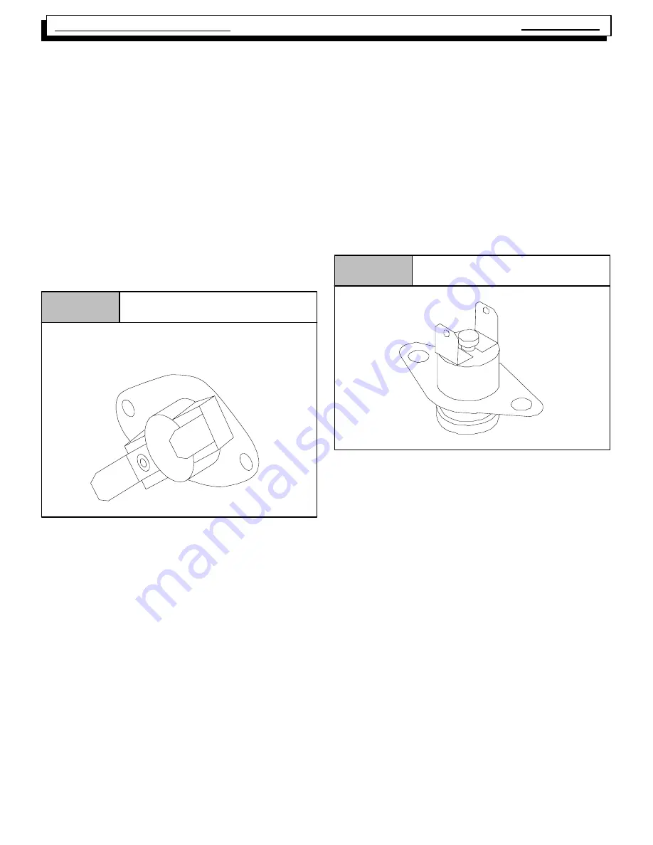
Typical Limit Switch
Figure 11
To verify this, the cut--out (opening) point of the switch should
be checked (using a thermocouple type thermometer con-
nected to the face of the switch) as follows:
1. Operate furnace for several minutes.
2. Block return air grille(s) to furnace.
3. Observe temperature at which switch opens (burner
operation ceases).
4. Remove blockage from return grille(s).
5. Observe temperature at which switch closes (burner
operation resumes).
6. Compare readings with the limit setting listed in the
appropriate chart for the model you are servicing.
If switch is opening within the specified range, then it is sim-
ply doing its job, and the cause of the over--temperature must
be determined and corrected.
If, however, the switch is found to be opening prematurely,
then it should be replaced. When replacing ANY limit switch,
use ONLY a switch of EXACTLY the same temperature set-
ting. Use of a different temperature limit switch can create a
dangerous situation. Some of the main limit switches used
in this series are SIMILAR IN APPEARANCE. DIFFERENT
TEMPERATURE SETTINGS, HOWEVER, ARE USED for
different models. Be certain you have the correct control for
the model you are servicing.
ROLL OUT LIMITS
Those “Normally Closed” unit switches (wired in series with
the Main Limit switch) on the top are mounted on the bottom
(left & right) of the burner box.
The switches are manual reset type. When replacing this
switch, be absolutely certain the correct one is used.
Typical Roll Out Limit Switch
Figure 12
CAUTION
NEVER use an automatic reset roll out switch to replace
a manual reset type roll out switch.
Doing so may cause potentially unsafe and/or intermit-
tent operation.
The roll out switch monitors the temperature inside the burn-
er box, and interrupts furnace (burner) operation when its
temperature indicates flame roll out has occurred.
If the roll out switch has opened, the cause must be deter-
mined. Some possible reasons for flame roll out include a re-
stricted primary or secondary heat exchanger or over fired
furnace.
MANUAL RESET SWITCH MODELS
Furnace models which are equipped with a Honeywell
ST9162A Fan timer/furnace control use a manual reset roll
out switch. Once the roll out switch has opened, burner op-
eration will be prevented until the roll out switch is “Manually
Reset” by pressing the red button located on the switch.
While the roll out switch is open, (Depending upon the partic-
ular model) the combustion blower and/or circulating blower
will be energized continuously.


