Technical support
:
P3
3
Hardware Installation
The associated hardware configuration is shown as following steps.
Step 1
: Checking operation mode of the WF-2572
It needs to set the DIP switch to the "OP" position (operating mode). As resetting the
power, it will cause the device to operate in the operation mode.
Step 2:
Power connection
Connect the power supply to power terminator of WF-2572.
Step 3:
USB port connection
WF-2572 supports USB communication for wireless configuration. If it does not need
to modify the parameter settings, this step can be omitted.
4
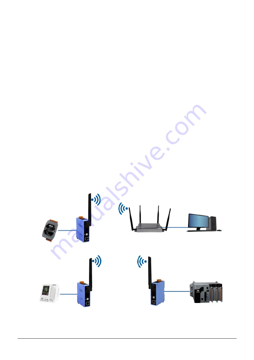
Connection Application
Users can use two WF-2572s or one WF-2572 module with the computer that supports
wireless network connection structure in the application. It can complete the purpose of
wireless network connection by this way.
Ethernet
WF-2572
(Infrastructure mode)
WF-2572
(Infrastructure mode)
Ethernet Device
Ethernet Device
Wi-Fi AP
PC
Ethernet
WF-2572
(Limit-AP mode)
Ethernet
Ethernet
PLC
2.4/5 GHz
Figure 1. Application of WF-2572


