


TPD/VPD Series HMI Device User Manual
Copyright © 2020 ICP DAS Co., Ltd. All Rights Reserved.
Page: 21
2. Hardware Information
This chapter provides a detailed description of the appearance, dimensions, pin assignments,
mount the hardware for the TPD/VPD series product.
2.1
Appearance
2.1.1
TPD-280/283 Series Models
Models supported include TPD-280, TPD-280U, TPD-280-H, TPD-280U-H, TPD-283, TPD-283U,
TPD-283-H and TPD-283U-H.
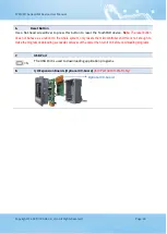
1.
2.8” TFT LCD with Touch Panel
2.
Power/GND/RS-485 Connector
(for TPD-280/280U/280-H/280U-H/283U/283U-H only)
The TouchPAD device is equipped with a removable terminal block connector is
designed for easy and robust wiring. For more detailed information regarding the pin
Section 2.2.1 TPD-280/283/430/433 Series Models
3.
Rotary Switch (0 ~ 9)
The Rotary Switch is used to set the configuration modes, as follows:
For TPD-280/280-H:
0. Run Only:
This mode is used for running programs.
1. Update Only:
This mode is used for updating programs.


