


PCI-82x Series Cards
Multifunction Boards
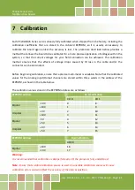
User Manual, Ver. 1.5, Jan. 2017, PMH-024-15, Page: 51
6.5.5
Read/Write MagicScan Counter Value
(Write/Read)wBase+0x0C Read/Write MagicScan Counter Value
This register is used to set/read the sampling value for MagicScan mode. The maximum value is
5000.
6.5.6
Write AI Pacer Configuration
(Write)wBase+0x10
Write the AI Pacer Configuration
Bit
F
E
D
C
B
A
9
8
7
6
5
4
3
2
1
0
Data
F0
S4
S3
S2
S1
S0
x
x
G1
G0
M5
M4
M3
M2
M1
M0
This register is used to set/read the Analog Input configuration for Pacer mode. The configuration
parameters include the Gain code, the Mode (single-ended or differential), and the channel number.
Clearing the FIFO(Bit F)
Write a value of 1 to F0 to clear the FIFO Data. The status of the FIFO will then be changed to empty.
Scan Channel Sequence Control (Bits A to E)
The following is an example of how to control the Scan Channel Sequence:
wChannels = 4
outpw( wBase+0x14,(0x0001|(wChannels-1)<<3));
//Set the Base Frequency and Total Scan Channels
outpw(wBase +0x08,100);
//Set the Sampling Rate
outpw(wBase+0x10,0x8032|(0<<10));
//Set the first channel number to 2,
outpw(wBase+0x10,0x8030|(1<<10));
//Set the second channel number to 0,
outpw(wBase+0x10,0x8037|(2<<10));
//Set the third channel number to 7,
outpw(wBase+0x10,0x8034|(3<<10));
//Set the four channel number to 4,
CH2
CH0
CH7
CH4


