


I-7540D CAN-Ethernet Gateway User’s Manual (Version 1.8, March/2021)
13
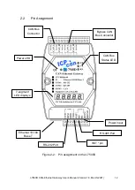
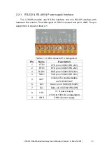
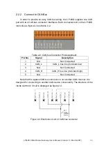
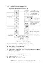
2.2.1 RS-232 & RS-485 & Power supply Interface
The I-7540D provides one RS-232 interface and one RS-485 interface with
hardware flow control. The GND-signal of COM1 is shared with pin-9, GND. The pin
assignment is shown in table 2-1.
Table 2-1: COM Connector Pin Assignment
Pin
Name
Description
1
CTS1
CTS pin of COM1 (RS-232)
2
RTS1
RTS pin of COM1 (RS-232)
3
RXD1
RXD pin of COM1 (RS-232)
4
TXD1
TXD pin of COM1 (RS-232)
5
INIT*
Initial pin for enable/disable
AUTOEXEC.BAT
6
D2+
Data+ pin of COM2 (RS-485)
7
D2-
Data- pin of COM2 (RS-485)
8
VS+
V+ of power supply
(+10V to +30V DC unregulated)
9
GND
GND of power supply