
GW-7553-B / GW-7553-M PROFIBUS/Modbus TCP Gateway User Manual
(Version 1.35, May/2017)
PAGE: 82
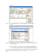
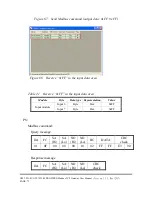
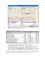
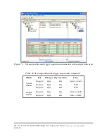
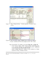
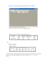
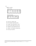
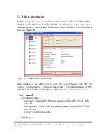
DA: Device Address-0x01
FC: Function Code-0x02:read DI
SA(Hi): Start Address(Hi byte)-0x00
SA(Lo): Start Address(Lo byte)-0x00
NO(Hi): No. Of points(Hi byte)-0x00
NO(Lo): No. Of points (Lo byte)-0x10
BC: Byte Count-0x02
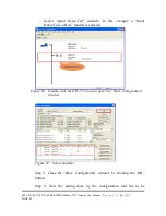
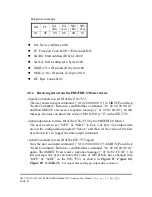
4.10.4 Using PROFIBUS DP-V1 to write data from a PROFIBUS Master
Device
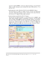
--Send Command to read AI of the GW-7553
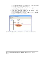
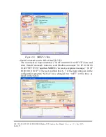
The user needs to input command (” 01 04 00 00 00 01”) in MBRTU and
click <Send Command> button to send Modbus command: “01 04 00 00 00
01 31 CA” and then MBRTU can receive response message (” 01 04 02 00 00
B9 30”). In this message, the user can know the value of AI0 is “0x00,0x00”
in the GW-7553.
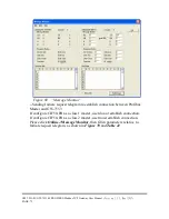
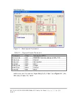
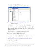
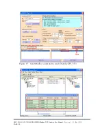
4.10.5 Data Exchange example – Modbus TCP
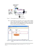
4.11 Data exchange example—Modbus TCP
In this example a Modbus Master device simulated by a PC program sends query
message and receives response message from a PROFIBUS Master via the GW-
7553 gateway.
In the following examples the CIF50-PB PROFIBUS Master card from Hilscher is
used. The configuration and communication is done by the program “SyCon”
provided by Hilscher.
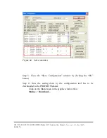
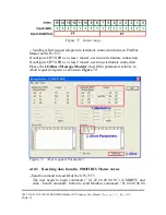
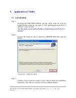
Step 1: Copy the GSD file and assign the GW-7553 a valid station address
(Please refer to the section 4.2 GSD file).
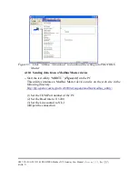
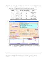
Step 2: Connect GW-7553 and PC by
Figure 77
.


