GW-7553-B / GW-7553-M PROFIBUS/Modbus TCP Gateway User Manual
(Version 1.35, May/2017)
PAGE: 44
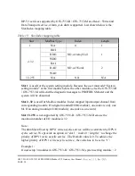
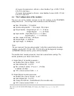
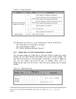
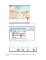
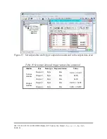
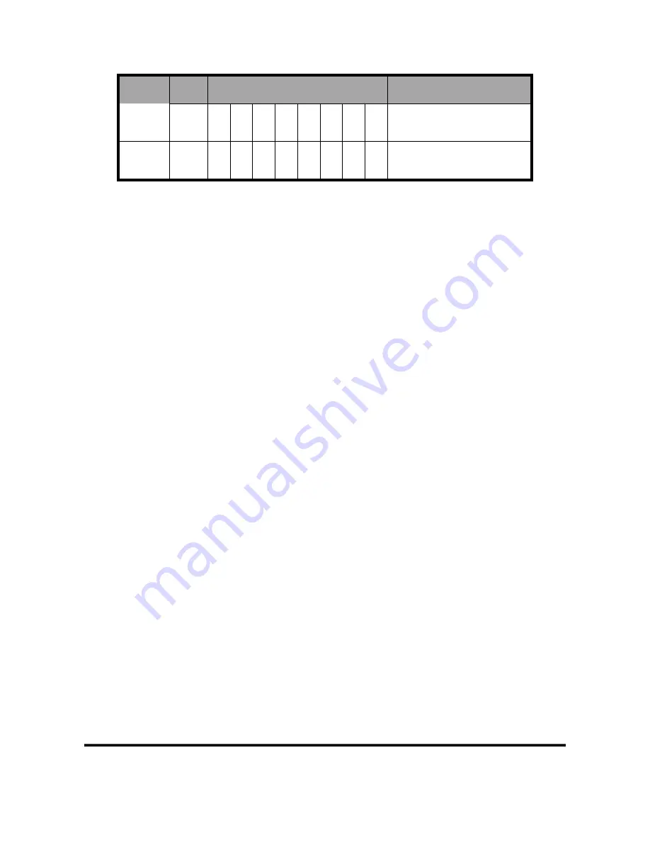
Module Byte
Bit Position
Description
2
Output module select
Output
module
3~239
Output data
●
Data output command(byte 0)
a.
When Modbus type is Master
When this byte is changed, PROFIBUS Master device will send data
of output module to DO/AO data of GW-7553-B / GW-7553-M and
then GW-7553-B / GW-7553-M will send query message to Modbus
Slave device for change data or output state of Modbus Slave device.
b.
When Modbus type is Slave
When this byte is changed, PROFIBUS Master device will send data
of output module to DO/AO data of GW-7553-B / GW-7553-M.
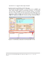
PS: When the user use this byte to trigger “data output command”, the
user must increase this byte in order (ex: 0->1, 1->2,…, 255->0) or else
the GW-7553-B / GW-7553-M will send a diagnostic message to the
PROFIBUS Master (please refer section 4.5 Diagnostic messages).
●
Control bit(byte 1)
DC(bit 0)
:
When this bit is set (DC=1), diagnostic messages sent by the
GW-7553-B / GW-7553-M module will all be cleared.
SM(bit 1)
:
When this bit is set (SM=1), the GW-7553-B / GW-7553-M
will enter setup mode. The utility can communicate with the
GW-7553-B / GW-7553-M in this mode.
When this bit is ''0'' (SM=0), the GW-7553-B / GW-7553-M
will enter normal operation mode. The GW-7553-B / GW-
7553-M can communicate with Modbus device in this mode.
Bit 2~7
:
The remaining bits have to be set to zero.
●
Output module select(byte 2)
When this byte is „0‟ and the user change data output command(byte 0),
it will trigger all data output command of output modules.


