background image


ECAN-240-FD (Modbus TCP to 2-port CAN FD Gateway) User Manual 

Version 1.0.0 

Page

60 


Copyright © 2022 ICP DAS Co., Ltd. All Rights Reserved    E-mail: [email protected] 

Appendix B. Glossary 

1.  ARP (Address Resolution Protocol) 

The Address Resolution Protocol (ARP) is a telecommunication protocol that is used to convert 

an IP address to a physical address, such as an Ethernet address.   


Consider two machines A and B that share the same physical network. Each has an assigned IP 

address IPA and IPB, and a MAC address, MACA and MACB. The goal is to devise a low-level 

software application that hides the MAC addresses and allows higher-level programs to work 

only with the IP addresses. Ultimately, however, communication must be carried out by the 

physical networks using whatever MAC address scheme the hardware supplies.   


Suppose machine a wants to send a packet to machine B across a physical network to which 

they are both attached, but an only has the Internet address for B, IP

B

. The question arises: how 

does A map that address to the MAC address for B, MAC

B

?   


ARP provides a method of dynamically mapping 32-bit IP address to the corresponding 48-bit 

MAC address. The term dynamic is used since the mapping is performed automatically and is 

normally not a concern for either the application user or the system administrator. 


2.  RARP (Reverse Address Resolution Protocol) 

RARP provides a method of dynamically mapping 48-bit MAC address to the corresponding 

32-bit IP address. RARP has now been replaced by the Bootstrap Protocol (BOOTP) and the 

modern Dynamic Host Configuration Protocol (DHCP). 


Summary of Contents for ECAN-240-FD

Page 1: ...CP to 2 port CAN FD Gateway User Manual Version 1 0 0 Page 1 Copyright 2022 ICP DAS Co Ltd All Rights Reserved E mail service icpdas com User Manual Version 1 0 0 July 2022 ECAN 240 FD Modbus TCP to 2...

Page 2: ...OR ECAN 240 FD 14 3 1 CONNECTING THE POWER SUPPLY AND THE HOST PC 14 3 2 CONFIGURING THE NETWORK SETTINGS 16 3 3 CONFIGURING THE CAN PORT 18 3 4 SELF TEST 20 4 WEB CONFIGURATION 23 4 1 LOGGING IN TO T...

Page 3: ...ICAL APPLICATIONS 57 6 1 MODBUS GATEWAY 57 APPENDIX A TROUBLESHOOTING 58 A 1 HOW DO I RESTORE THE WEB PASSWORD FOR THE MODULE TO THE FACTORY DEFAULT PASSWORD 58 APPENDIX B GLOSSARY 60 1 ARP ADDRESS RE...

Page 4: ...e of this product ICP DAS reserves the right to change this manual at any time without notice The information furnished by ICP DAS is believed to be accurate and reliable However no responsibility is...

Page 5: ...aking life more convenient In order to provide additional access to IoT applications related to industry based on the CAN bus ICPDAS has developed a new Ethernet product the ECAN 240 FD The ECAN 240 F...

Page 6: ...bit rates from 10 kbps to 1000 kbps Built in switchable 120 ohm terminal resistor for CAN Bus Supports TCP server mode operation Supports UDP responder for device discovery UDP Search Static IP or DH...

Page 7: ...logy Web server technology enables the ECAN 240 FD to be configured via a standard web browser interface e g Google Chrome Internet Explorer or Firefox etc This means that it is easy to check the conf...

Page 8: ...ield 100 10000 kbps Terminal Resistor DIP switch for the 120 terminal resistor Isolation 3 kV VDC for DC to DC 2500 Vrms for photo couple Specification ISO 11898 2 CAN 2 0 A B and FD Ethernet Interfac...

Page 9: ...tects the CAN error warning error passive and bus off status on the CAN1 bus this LED flashes once per 100 ms ST2 Red If the ECAN 240 FD detects the CAN error warning error passive and bus off status...

Page 10: ...Mbps the 10 100M LED Orange indicator will be illuminated 3 9 pin D Sub male connector Pin assignments of CAN Bus Connector Pin Description 1 N A 2 CAN Low 3 CAN Ground 4 N A 5 N A 6 CAN Ground 7 CAN...

Page 11: ...Manual Version 1 0 0 Page 11 Copyright 2022 ICP DAS Co Ltd All Rights Reserved E mail service icpdas com 6 10 to 30 VDC Terminal Block The ECAN 240 FD is equipped with a 10 VDC to 30 VDC 3 pin termina...

Page 12: ...Gateway User Manual Version 1 0 0 Page 12 Copyright 2022 ICP DAS Co Ltd All Rights Reserved E mail service icpdas com 2 3 Dimensions The following diagrams provide the dimensions of the ECAN 240 FD m...

Page 13: ...ISO 11898 2 each terminal resistor should be 120 or between 96 and 144 The bus topology and the positions of these terminal resistors are shown below The ECAN 240 FD module includes two CAN ports and...

Page 14: ...rocedures must first be fully completed Follow the procedure described below 3 1 Connecting the Power Supply and the Host PC 1 Ensure that the network settings on your PC are configured correctly 2 En...

Page 15: ...o Ltd All Rights Reserved E mail service icpdas com 4 Connect both thet ECAN 240 FD and the Host computer to the same sub network or the same Ethernet Switch and then power on the ECAN 240 FD Refer to...

Page 16: ...oad show php num 6710 nation TW kind1 model kw esearch Note The version of the eSearch Utility have to v1 3 0 or later 2 Open the eSearch Utility and then click the Search Server button to search for...

Page 17: ...ICP DAS Co Ltd All Rights Reserved E mail service icpdas com 5 Wait 2 seconds and click Search Server button again to ensure the ECAN 240 FD is working well with new configuration Factory Default Set...

Page 18: ...You can right click the IP address field and click the Copy to Clipboard to copy the IP address 2 When the login screen is displayed enter the password use the default password admin in the login pas...

Page 19: ...ECAN 240 FD Modbus TCP to 2 port CAN FD Gateway User Manual Version 1 0 0 Page 19 Copyright 2022 ICP DAS Co Ltd All Rights Reserved E mail service icpdas com...

Page 20: ...2 Download and install the Modbus Poll test program at below link https www modbustools com download html 3 Double click the Modbus Poll shortcut to open 4 Select the Read Write Definition item from...

Page 21: ...opyright 2022 ICP DAS Co Ltd All Rights Reserved E mail service icpdas com 7 Select the Connect item from the Connection menu to open the Connection Setup dialog box 8 Configure the Ipv4 address and T...

Page 22: ...right 2022 ICP DAS Co Ltd All Rights Reserved E mail service icpdas com 9 Write a CAN CAN FD message to CAN1 Tx FIFO 1 address 00000 10 Read a CAN CAN FD message from CAN2 Rx FIFO 1 address 04096 11 I...

Page 23: ...m any computer that has an Internet connection Step 1 Open a new browser window Open a web browser for example Google Chrome Firefox or Internet Explorer which are reliable and popular Internet browse...

Page 24: ...word After the main login page is displayed enter a password the factory default password is admin and then click the Submit button to continue Note For the first time to use the ECAN 240 FD device yo...

Page 25: ...the ECAN 240 FD hardware and software The software and hardware information section includes information related to the Model Name the current Firmware version the IP Address the current position of t...

Page 26: ...AS Co Ltd All Rights Reserved E mail service icpdas com 4 3 CAN Port Page 4 3 1 Port1 2 Settings The Port1 2 Settings section provides functions allowing items such as CAN port and filter settings to...

Page 27: ...rame Disable disable this reject function Enable enable this reject function Disable Reject Remote Extended Frame Reject remote extended CAN CAN FD frame Disable disable this reject function Enable en...

Page 28: ...8 Copyright 2022 ICP DAS Co Ltd All Rights Reserved E mail service icpdas com identifier extended Mask ID extended Filter ID extended Mask ID Update Settings Click this button to save the revised sett...

Page 29: ...isable Enable the Specific CAN ID function of this port Disable ID 00 ID 09 Specific CAN ID 00 09 settings hexadecimal format When received CAN frame s ID matched these Specific CAN ID 00 09 settings...

Page 30: ...ddress Subnet Mask and Default Gateway values are the most important network settings and should always correspond to the LAN configuration If they do not match the ECAN 240 FD module will not operate...

Page 31: ...on of the IP address is used to identify the local network or subnet Default Gateway This parameter is used to assign the subnet mask for the ECAN 240 FD device The subnet mask indicates which portion...

Page 32: ...das com 4 4 1 1 Manual Configuration When using manual configuration the network settings should be assigned in the following manner Step 1 Select the Static IP option from the Address Type drop down...

Page 33: ...cpdas com 4 4 1 2 Dynamic Configuration Dynamic configuration is very easy to perform If a DHCP server is connected to you network a network address can be dynamically configured by using the followin...

Page 34: ...no activity on the network for a specific period of time the system will be rebooted based on the configured system timeout value Timeout value range 30 to 65535 seconds Disable 0 300 Web Auto logout...

Page 35: ...rocedure to reset all parameters to their original factory default settings Step 1 Click the Restore Defaults button to reset the configuration Step 2 Click the OK button in the message dialog box Ste...

Page 36: ...il service icpdas com The following is an overview of the factory default settings Factory Default Settings Network Settings Basic Settings IP Address 192 168 255 1 Alias Modbus CAN FD Gateway Address...

Page 37: ...mail service icpdas com 4 5 Filter Page The Accessible IP Settings page is used to query or edit the IP Filter List The IP Filter List restricts the access of packets based on the IP header If one or...

Page 38: ...iption Add IP To The List Add an IP address to the IP Filter List Add Range IP Mask IP Add an IP address range to the IP Filter List Delete IP Number Delete a specific IP address from the IP Filter Li...

Page 39: ...status of the CAN port for the ECAN 240 FD module CAN Status Bit Symbol Value Description 0 RX CAN1 CAN2 receive software buffer status 0 Receive software buffer underrun 1 Receive software buffer ove...

Page 40: ...om 5 EP CAN1 2 Error passive status 0 The CAN is in Error_Active state 1 The CAN is in the Error_Passive state 6 BO CAN1 2 Bus Off status 0 The CAN is not in Bus_OFF state 1 The CAN is in the Bus_OFF...

Page 41: ...ab the Change Password page will be displayed To change a password first enter the old password in the Current password field use the default password admin and then enter a new password in the New pa...

Page 42: ...way User Manual Version 1 0 0 Page 42 Copyright 2022 ICP DAS Co Ltd All Rights Reserved E mail service icpdas com 4 8 Logout Page After clicking the Logout tab you will be immediately logged out from...

Page 43: ...multiple output registers that are used to store one or many CAN CAN FD messages that want to be transmitted out in output data area 5 1 Modbus CAN Mapping Table Users can access the CAN CAN FD messag...

Page 44: ...use Modbus Function Code 0x04 to get CAN CAN FD messages and CAN status from ECAN 240 FD Input Data Area of ECAN 240 FD Protocol Base Address 0xxxx Description 00000 00399 CAN1 Rx FIFO Message 1 10 Re...

Page 45: ...ype 0 STD or 1 EXT Bit 4 rtr CAN Frame Type 0 DATA or 1 REMOTE Bit 0 3 dlc Data Length Code NOTE1 STD standard frame EXT extended frame 3 4 Bit 29 31 Reserved Bit 0 28 id CAN Frame Identifier 5 CAN Da...

Page 46: ...dlc Data Length Code of CAN CAN FD frame data length dlc Hexadecimal Frame data length Decimal dlc Hexadecimal Frame data length Decimal 0x0 0 0x8 8 0x1 1 0x9 12 0x2 2 0xA 16 0x3 3 0xB 20 0x4 4 0xC 24...

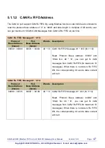
Page 47: ...ess 0xxxx PLC Base Address 3xxxx Words Description 00000 00399 30001 30400 40 10 CAN1 Rx FIFO Message 1 10 N 1 10 Read Protocol Base Address 00000 and Word No 40 N you can get N CAN messages from CAN1...

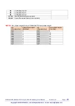
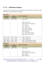
Page 48: ...514 2 CAN1 Status Bit 9 31 reserved Bit 8 Modbus Tx FIFO overflow Bit 7 reserved Bit 6 CAN bus off Bit 5 CAN error passive Bit 4 CAN error warning Bit 2 3 reserved Bit 1 CAN Tx FIFO overflow Bit 0 CAN...

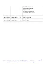
Page 49: ...s Reserved E mail service icpdas com Bit 5 CAN error passive Bit 4 CAN error warning Bit 2 3 reserved Bit 1 CAN Tx FIFO overflow Bit 0 CAN Rx FIFO overflow 04610 04611 34611 34612 2 CAN2 Tx data count...

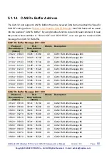
Page 50: ...Buffer Message 02 01144 01183 31145 31184 40 CAN1 Rx Buffer Message 03 01184 01223 31185 31224 40 CAN1 Rx Buffer Message 04 01224 01263 31225 31264 40 CAN1 Rx Buffer Message 05 01264 01303 31265 3130...

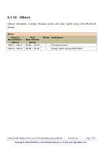
Page 51: ...ts Reserved E mail service icpdas com 5 1 1 5 Others Others information including firmware version and rotary switch value of ECAN 240 FD module Others Protocol Base Address 0xxxx PLC Base Address 3xx...

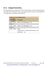
Page 52: ...FO Reboot System Restore default setting and Clear CAN status information for user to use Modbus Function Code 0x10 to set CAN CAN FD Tx messages and module status of ECAN 240 FD Output Data Area of E...

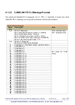
Page 53: ...r 1 EXT Bit 4 rtr CAN Frame Type 0 DATA or 1 REMOTE Bit 0 3 dlc Data Length Code NOTE1 STD standard frame EXT extended frame 3 4 Bit 29 31 Reserved Bit 0 28 id CAN Frame Identifier 5 CAN Data 0 1 High...

Page 54: ...service icpdas com NOTE1 dlc Data Length Code of CAN CAN FD frame data length dlc Hexadecimal Frame data length Decimal dlc Hexadecimal Frame data length Decimal 0x0 0 0x8 8 0x1 1 0x9 12 0x2 2 0xA 16...

Page 55: ...CAN CAN FD Messages to CAN1 2 Tx FIFO at one time CAN1 Tx FIFO Message 1 5 Protocol Base Address 0xxxx PLC Base Address 4xxxx Words Description 00000 00179 40001 40180 36 5 CAN1 Tx FIFO Message 1 5 N...

Page 56: ...tting and Clear CAN status of ECAN 240 FD module Others Protocol Base Address 0xxxx PLC Base Address 4xxxx Words Description 02049 02049 42050 42050 1 System Reboot 0x55AA Reboot system Others do noth...

Page 57: ...r provides some examples of typical scenarios for the ECAN 240 FD module including applications focused on the Modbus Gateway etc 6 1 Modbus Gateway The ECAN 240 FD module is a Modbus TCP to CAN CAN F...

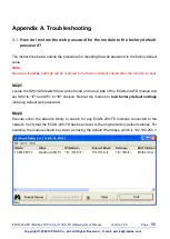
Page 58: ...that ALL settings will be restored to the factory default values after the module is reset Step 1 Locate the SW1 SW2 switch that can be found on the top side of the ECAN 240 FD module and set SW2 to F...

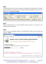
Page 59: ...to open the Configure Server UDP dialog box and modify the basic settings as necessary e g the IP Mask and Gateway addresses and then click the OK button to save the new settings Step 4 Reset the SW1...

Page 60: ...er communication must be carried out by the physical networks using whatever MAC address scheme the hardware supplies Suppose machine a wants to send a packet to machine B across a physical network to...

Page 61: ...l layer Local Area Network LAN technology in use today 5 Firmware Firmware is an embedded software program or set of instructions programmed on a device that provides the necessary instructions for ho...

Page 62: ...way or a router 10 Gateway Computers that interconnect two networks and pass packets from one to the other are called Internet Gateways or Internet Routers Gateways route packets that are based on the...

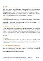
Page 63: ...and a port number is called a socket 15 TCP Transmission Control Protocol TCP is a set of rules used in combination with the Internet Protocol to send data in the form of message units between comput...

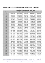
Page 64: ...1153 846 1132 075 1111 111 1090 909 50 1071 429 1052 632 1034 483 1016 949 1000 000 55 983 6066 967 7419 952 381 937 500 923 0769 60 909 0909 895 5224 882 3529 869 5652 857 1429 65 845 0704 833 3333 8...

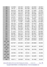
Page 65: ...304 5685 303 0303 301 5075 300 000 195 298 5075 297 0297 295 5665 294 1176 292 6829 200 291 2621 289 8551 288 4615 287 0813 285 7143 205 284 3602 283 0189 281 6901 280 3738 279 0698 210 277 7778 276...

Page 66: ...ge 66 Copyright 2022 ICP DAS Co Ltd All Rights Reserved E mail service icpdas com Appendix D Revision History This chapter provides revision history information to this document The table below shows...

Reviews: