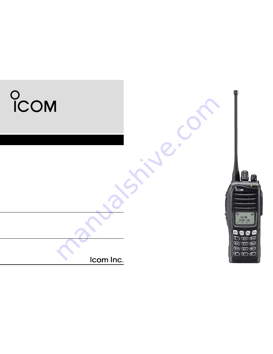
INSTRUCTION MANUAL
This device complies with Part 15 of the FCC Rules. Operation is subject to the condition that this device does not cause harmful interference.
iF4163T/S
iF4161T/S/DT/DS
UHF TRANSCEIVER
iF3163T/S
iF3161T/S/DT/DS
VHF TRANSCEIVER
Page 1: ...s device complies with Part 15 of the FCC Rules Operation is subject to the condition that this device does not cause harmful interference iF4163T S iF4161T S DT DS UHF TRANSCEIVER iF3163T S iF3161T S...
Page 2: ...DEFINITIONS WORD DEFINITION RDANGER Personal death serious injury or an explo sion may occur RWARNING Personal injury fire hazard or electric shock may occur CAUTION Equipment damage may occur NOTE If...
Page 3: ...C or above 140 F 60 C The basic operations transmission and reception of the transceiver are guaranteed within the specified operating temperature range However the LCD display may not oper ate corre...
Page 4: ...nce by one or more of the following meas ures Reorient or relocate the receiving antenna Increase the separation between the equipment and re ceiver Connect the equipment into an outlet on a circuit d...
Page 5: ...hannel selection 12 Call procedure 13 Receiving and transmitting 13 User set mode 16 Emergency transmission 16 Man Down Emergency Call 16 Scrambler function 17 Stun function 17 Automatic Key Lock func...
Page 6: ...antenna Battery pack Belt clip Connector cover with screw Accessory attachments D Flexible antenna Connect the supplied flexible antenna to the antenna connector CAUTION NEVER HOLD the antenna when c...
Page 7: ...ttach the battery pack when the transceiver is wet or soiled This may result water or dust getting into the transceiver battery pack and may result in the transceiver being damaged q w Battery release...
Page 8: ...n the screw q w Multi connector Connector cover CAUTION Attach the connector cover when the optional equipment is not used Otherwise the terminals of the multi connec tor may be shorted by metal objec...
Page 9: ...mmed by your dealer p 6 t PTT SWITCH PTT Push and hold to transmit release to receive y DEALER PROGRAMMABLE KEYS Side2 Side3 Desired function can be programmed independently by your dealer p 6 u 10 KE...
Page 10: ...power ON OFF and adjusts the audio level Function display SET CALA TXCU TXC q t i u y r e w o 0 q SIGNAL STRENGTH INDICATOR Indicates relative signal strength level w LOW POWER INDICATOR Appears when...
Page 11: ...mode 0 KEY INDICATOR Indicate the programmed function of the front panel keys P0 P1 P2 and P3 Programmable function keys The following functions can be assigned to EMR Side1 Side2 Side3 P0 P1 P2 and P...
Page 12: ...riod has passed Push and hold this key for 1 sec to indicate the scan list then push CH Up or CH Down to select the desired list SCAN ADD DEL TAG KEY SCAD Push to add or delete the selected channel to...
Page 13: ...r and OPT 1 2 3 Push and hold for 1 sec again to turn the lock function OFF LONE WORKER KEY LONE Push to turn the Lone Worker function ON or OFF If the Lone Worker function is activated the Emergency...
Page 14: ...l transmission is necessary before you call another station depending on your signaling system Call A and or Call B may be available when your system employs selective Individual Group calls Ask your...
Page 15: ...o toggle the encryption transmission function ON and OFF COMPANDER KEY COMP Push to toggle the compander function ON and OFF The compander function reduces noise components from the transmitting audio...
Page 16: ...1 P2 P3 e When the PASSWORD indication does not clear after inputting 6 digits the input code number may be incorrect Turn the power off and start over in this case D Battery type selection The batter...
Page 17: ...mmed 16 zones can be selected D Voting operation The transceiver automatically starts scanning when a zone specified for the voting operation is selected The voting scan detects the S meter of the rep...
Page 18: ...g and transmitting NOTE Transmitting without an antenna may damage the transceiver See p 1 for accessory attachments Receiving q Rotate VOL to turn the power ON w Push CH Up or CH Down or rotate ROTAR...
Page 19: ...ermined by the penalty timer D TX code channel selection If the transceiver has TX Code CH Select assigned to it the indication can be toggled between the operating channel number or name and TX code...
Page 20: ...CH Select to set Return to the stand by mode i Push Call to transmit USING TX CODE ENTER KEY q After pushing TX Code CH Select push CH Up or CH Down or push TX Code CH Up or TX Code CH Down to select...
Page 21: ...ide2 or Side3 and P0 activate while in the user set mode regardless of the assigned key functions Emergency transmission When Emergency is pushed for the specified time period an emergency signal is a...
Page 22: ...ime period has passed without operation during standby condition While the lock function is ON push and hold Lock for 1 sec to turn the function OFF When 0 is programmed this function is not available...
Page 23: ...r leave battery packs in areas with temperatures above 60 C 140 F High tempera ture buildup in the battery such as could occur near fires or stoves inside a sun heated car or in direct sunlight may ca...
Page 24: ...y place with the temperature range as below 20 C to 50 C 4 F to 122 F within a month 20 C to 35 C 4 F to 95 F within three months 20 C to 20 C 4 F to 68 F within a year D Charging caution R DANGER NEV...
Page 25: ...of the AC adapter AC adapter A different type or no AC adapter is supplied de pending on the version Transceiver Battery pack Turn power OFF D Regular charging with the BC 171 The optional BC 171 prov...
Page 26: ...06 The optional BC 119N provides rapid charging of the Li Ion battery pack Charging period Approx 3 hours with BP 232N The following items are additionally required AD 106 charger adapter purchase sep...
Page 27: ...adapters purchase separately An AC adapter BC 157 or the DC power cable OPC 656 Transceiver Battery pack AD 106 charger adapters are installed in each slot DC power cable OPC 656 Connect with the DC p...
Page 28: ...ose r And hook the battery cover release hook until it makes a click sound t Fig 3 CAUTION When installing batteries make sure they are all the same brand type and capacity Also do not mix new and old...
Page 29: ...he base clip in the direction of the arrow until the base clip is locked and makes a click sound e Clip the belt clip to a part of your belt And insert the transceiver into the belt clip until the bas...
Page 30: ...inch the clip q and slide the base clip in the direction of the arrow w q w CAUTION HOLD THE TRANSCEIVER TIGHTLY WHEN HANGING OR DETACHING THE TRANSCEIVER FROM THE BELT CLIP Otherwise the transceiver...
Page 31: ...agram above To maximize the readability of your transmitted signal voice hold the microphone approx 5 to 10 cm 2 to 4 inches from your mouth and speak in a normal voice level To attach Attach the conn...
Page 32: ...ed separately Charging time approx 3 hours when BP 232N is attached BC 160 desktop charger BC 145 ac adapter For rapid charging of battery pack An AC adapter is sup plied with the charger depending on...
Page 33: ...r microphone HM 170GP speaker microphone GPS speaker microphone for BIIS and Digital modes op eration HS 94 HS 95 HS 97 headset VS 1SC vox ptt case HS 94 Ear hook type HS 95 Neck arm type HS 97 Throat...
Page 34: ...and revolving clip VS 1SC Water protection cover PTT switch MIC VOX gain adjusting pot VOX PTT select switch VOX gain and delay adjustment q Attach the connector of the VS 1SC into the multi con necto...
Page 35: ...om 0 5 to 3 0 sec 0 5 sec step for a convenient interval before returning to receive 0 5 sec min default X TXC SET CALA SET TXCU TXC CALA SET TXCU TXC VOX DLY0 5 VOX DLY3 0 3 0 sec max X TXC SET Side2...
Page 36: ...N and MB 96F Rechargeable Li Ion Battery Pack BP 230N and BP 232N Alkalies Battery Case BP 240 and Speaker microphone HM 131SC HM 159SC HM 169 and HM 170GP To ensure that your expose to RF electromag...
Page 37: ...terference turn off the radio in areas where signs are posted to do so DO NOT operate the transmitter in areas that are sensitive to electromagnetic radiation such as hospitals aircraft and blasting s...
Page 38: ...MEMO...
Page 39: ...MEMO...
Page 40: ...1 1 32 Kamiminami Hirano ku Osaka 547 0003 Japan A 6638H 1EX w Printed in Japan 2007 2009 Icom Inc Printed on recycled paper with soy ink...