background image

INSTRUCTION MANUAL

This device complies with Part 15 of the FCC Rules. Op-
eration is subject to the condition that this device does not 
cause harmful interference.

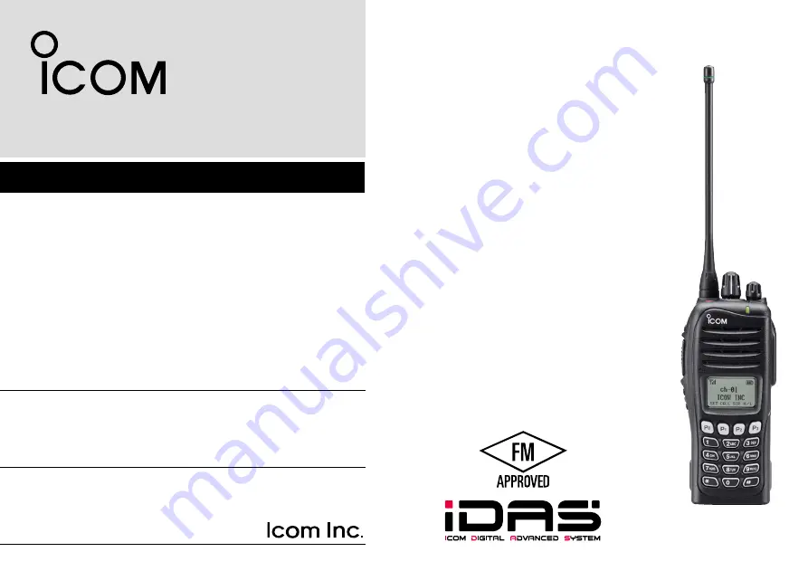
The photo shows the 
UHF transceiver.

iF4161DT

UHF TRANSCEIVER

iF4161DS

iF3161DT

VHF TRANSCEIVER

iF3161DS

Summary of Contents for IC-F3161DT

Page 1: ...mplies with Part 15 of the FCC Rules Op eration is subject to the condition that this device does not cause harmful interference The photo shows the UHF transceiver iF4161DT UHF TRANSCEIVER iF4161DS i...

Page 2: ...property rights including patent rights copyrights and trade secrets of Digital Voice Systems Inc This voice coding Technology is licensed solely for use within this Communications Equipment The user...

Page 3: ...rs FM ap proval CAUTION Changes or modifications to this transceiver not expressly approved by Icom Inc could void your author ity to operate this transceiver under FCC regulations DO NOT push PTT whe...

Page 4: ...marking on the label The approval rating for these models are Intrinsically safe Class I II III Division 1 Groups D E F G Nonincendive Class I Division 2 Groups A B C D WARNING NEVER charge the BP 23...

Page 5: ...e function keys 6 3 BASIC OPERATION 11 18 Turning power ON 11 Channel selection 11 Call procedure 13 Receiving and transmitting 13 User set mode 16 Scrambler function 16 Stun function 16 Emergency tra...

Page 6: ...le antenna This illustration is for the UHF type Accessory attachments D Flexible antenna Connect the supplied flexible antenna to the antenna connector CAUTION NEVER carry the transceiver by holding...

Page 7: ...move or attach the battery pack when the trans ceiver is wet or soiled This may result water or dust get ting into the transceiver battery pack and may result in the transceiver being damaged q w Batt...

Page 8: ...onnector cover CAUTION Attach the connector cover when the optional equipment is not used Otherwise the terminals of the multi connec tor may be shorted by metal object etc and this could damage the t...

Page 9: ...mmed by your dealer p 6 t PTT SWITCH PTT Push and hold to transmit release to receive y DEALER PROGRAMMABLE KEYS Side2 Side3 Desired function can be programmed independently by your dealer p 6 u 10 KE...

Page 10: ...power ON OFF and adjusts the audio level Function display SET CALA TXCU TXC q t i u y r e w o 0 q SIGNAL STRENGTH INDICATOR Indicates relative signal strength level w LOW POWER INDICATOR Appears when...

Page 11: ...mode 0 KEY INDICATOR Indicate the programmed function of the front panel keys P0 P1 P2 and P3 Programmable function keys The following functions can be assigned to EMR Side1 Side2 Side3 P0 P1 P2 and P...

Page 12: ...riod has passed Push and hold this key for 1 sec to indicate the scan list then push CH Up or CH Down to select the desired list SCAN ADD DEL TAG KEY SCAD Push to add channel to or delete it from the...

Page 13: ...r and OPT 1 2 3 Push and hold for 1 sec again to turn the lock function OFF LONE WORKER KEY LONE Push to turn the Lone Worker function ON or OFF If the Lone Worker function is activated the Emergency...

Page 14: ...dealer which call is assigned to each key EMERGENCY KEY EMR Push and hold to transmit the emergency call The emergency call transmits with beeps the display does not change The transceiver can transm...

Page 15: ...ON and OFF COMPANDER KEY COMP Push to toggle the compander function ON and OFF The compander function reduces noise components from the transmitting audio to provide clear communication USER SET MODE...

Page 16: ...tting 6 digits the input code number may be incorrect Turn the power off and start over in this case Channel selection Several types of channel selections are available Methods may differ according to...

Page 17: ...e transceiver automatically starts scanning Scanning stops when receiving a call Depending on the pre setting When Rotary selector selects Operating channel CH Up CH Down are not available When Rotary...

Page 18: ...1 for accessory attachments Receiving q Rotate VOL to turn the power ON w Push CH Up or CH Down or rotate ROTARY SELEC TOR to select the conventional system channel in se quence Depending on the pre s...

Page 19: ...ermined by the penalty timer D TX code channel selection If the transceiver has TX Code CH Select assigned to it the indication can be toggled between the operating channel number or name and TX code...

Page 20: ...CH Select to set Return to the stand by mode i Push Call to transmit USING TX CODE ENTER KEY q After pushing TX Code CH Select push CH Up or CH Down or push TX Code CH Up or TX Code CH Down to select...

Page 21: ...Appears only when the external VOX unit is connected e Push and hold User Set Mode again to exit the User Set mode Scrambler function The voice scrambler function provides private communication betwee...

Page 22: ...g the call If your transceiver is programmed for Silent operation you can transmit an Emergency call without the beep sounding and the LED indicator lighting IMPORTANT It is recommended to set an emer...

Page 23: ...ion is ON push and hold Lock for 1 sec to turn the function OFF When 0 is programmed this function is not available Priority A channel selection When one of the following operations is performed the t...

Page 24: ...atures above 40 C 104 F High tempera ture buildup in the battery such as could occur near fires or stoves inside a sun heated car or in direct sunlight may cause the battery to rupture or catch fire E...

Page 25: ...35 C 4 F to 95 F within three months 20 C to 20 C 4 F to 68 F within a year D Charging caution R DANGER NEVER charge the battery pack in areas with extremely high temperatures such as near fires or st...

Page 26: ...ransceiver Battery pack AC adapter A different type or no AC adapter is supplied de pending on the version Turn power OFF D Regular charging with the BC 171 The optional BC 171 provides regular chargi...

Page 27: ...crews Screws supplied with the charger adapter AD 106 Plugs Sockets This illustration shows the BC 119N D Rapid charging with the BC 119N AD 106 The optional BC 119N provides rapid charging of the Li...

Page 28: ...D 106 charger adapters are installed in each slot DC power cable OPC 656 Connect with the DC power supply 13 8 V at least 7 A AC adapter Purchased separately Turn power OFF IMPORTANT Battery charging...

Page 29: ...the direction of the arrow until the base clip is locked and makes a click sound e Attach the battery pack p 2 r Clip the belt clip to a part of your belt And insert the transceiver into the belt cli...

Page 30: ...inch the clip q and slide the base clip in the direction of the arrow w q w CAUTION HOLD THE TRANSCEIVER TIGHTLY WHEN HANGING OR DETACHING THE TRANSCEIVER FROM THE BELT CLIP Otherwise the transceiver...

Page 31: ...the microphone approximately 5 to 10 cm 2 to 4 inches from your mouth and speak in a normal voice level To attach Attach the connector of the speaker microphone into the multi connector on the transc...

Page 32: ...160 desktop charger BC 145SA ac adapter For rapid charging of battery pack An AC adapter is sup plied with the charger Charging time Approximately 3 hours BC 171 desktop charger BC 147SA ac adapter F...

Page 33: ...quipment is designed for optimal performance when used with an Icom transceiver Icom is not responsible for the destruction or damage to an Icom transceiver in the event the Icom transceiver is used w...

Page 34: ...exit user set mode VOX Gain The VOX sensitivity level can be adjusted from OFF or 1 to 6 more sensitive VOX function is OFF X TXC SET CALA SET TXCU TXC CALA SET TXCU TXC VOX OFF VOX GAIN 3 VOX gain l...

Page 35: ...ing the FCC and IC re quirements for wireless RF exposure Belt Clip MB 93 MB 94 MB 96N and MB 96F Rechargeable Li ion Battery Pack BP 232FM and Speaker microphone HM 169IS CAUTION To ensure that your...

Page 36: ...lisation grand pu blic dans un environnement non contr l Cet appareil a t valu et jug conforme aux limites d expo sition aux RF de la FCC et d IC pour une utilisation grand pu blic En outre votre radi...

Page 37: ...e corps au moment d mettre et utiliser uniquement l at tache pour ceinture Icom illustr e la p 27 lorsque vous at tachez la radio votre ceinture ou autre chose de fa on vous assurer de ne pas provoque...

Page 38: ...MEMO...

Page 39: ...MEMO 1 2 3 4 5 6 7 8 9 10 11 12 13 14 15 16...

Page 40: ...1 1 32 Kamiminami Hirano ku Osaka 547 0003 Japan A 6831H 1EX w Printed in Japan 2010 2013 Icom Inc Printed on recycled paper with soy ink...

Reviews: