background image

General information

10

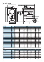
555 - 700 - 780 - 850 models

P2

P1

H2

P5

P4

P3

N7

N4

N9

N2

L2
L1

H1

H5

H4

H

L

L6

N2

N1

N9

N4

N7

Øc

H12

H6

H10

H9

H8

Øb

P

N6

N5

N1

N3

N8

N10

P7 P8

Dimensions

Description

u.m.

MONOLITE GT

120

140

180

250

320

420

555

700

780

850

H

mm

1811

1811

1811

2140

2140

2185

2294

2294

2294

2294

H1

mm

1715

1715

1715

1956

1956

1956

2021

2021

2021

2021

H2

mm

1335

1335

1335

1510

1510

1510

1532

1532

1532

1532

H4

mm

-

-

-

1953

1953

1955

2025

2025

2025

2025

H5

mm

-

-

-

2060

2060

2090

2189

2189

2189

2189

H6

mm

241

241

241

358

358

358

310

308

308

308

H8

mm

828

828

828

864

864

864

854

854

854

854

H9

mm

548

548

548

589

589

589

570

570

570

570

H10

mm

423

423

423

549

549

549

525

525

525

525

H12

mm

103

103

103

189

189

189

112

112

112

112

L

mm

994

994

994

1104

1104

1104

1188

1188

1188

1188

L1

mm

780

780

780

890

890

890

974

974

974

974

L2

mm

690

690

690

800

800

800

920

920

920

920

L6

mm

-

-

-

150

150

150

200

200

200

200

P

mm

1270

1587

1760

1765

2005

2300

2452

2452

2695

2695

P1

mm

851

1106

1106

1041

1281

1536

1560

1560

1810

1810

P2

mm

679

934

934

909

1149

1404

1436

1436

1686

1686

P3

mm

525

595

768

783

783

823

955

955

948

948

P4

mm

350

200

200

195

195

195

520

520

520

520

P5

mm

395

792

792

787

1027

1282

977

977

1227

1227

P7

mm

-

-

-

-

-

-

150

150

150

150

P8

mm

-

-

-

-

-

-

150

150

150

150

Øb

mm

150

150

187

205

205

205

225

270

270

270

Øc

mm

180

180

180

200

200

200

250

250

250

250

Fittings

Description

u.m.

MONOLITE GT

120

140

180

250

320

420

555

700

780

850

N1

DN/in

50

50

50

65

65

80

100

100

100

100

N2

DN/in

50

50

50

65

65

80

100

100

100

100

N1/N2

PN

6

6

6

6

6

6

6

6

6

6

N3

DN/in

1"

1"

1"

1"

1"

1/4”

1"

1"

1"

1"

N4

DN/in

1"

1"

1"

1"

1"

1"

1"

1"

1"

1"

N5

DN/in

-

-

-

-

-

-

1/2”

1/2”

1/2”

1/2”

N6

DN/in

1/2”

1/2”

1/2”

1/2”

1/2”

1/2”

1/2”

1/2”

1/2”

1/2”

N7

DN/in

3/4”

3/4”

3/4”

3/4”

3/4”

3/4”

3/4”

3/4”

3/4”

3/4”

N8

DN/in

1/2”

1/2”

1/2”

1/2”

1/2”

1/2”

1/2”

1/2”

1/2”

1/2”

N9

DN/in

50

50

50

65

65

80

100

100

100

100

N10

DN/in

3/4”

3/4”

1"

1"

1"

1"

1" 1/2

1" 1/2

1" 1/2

1" 1/2

Summary of Contents for MONOLITE 320 GT

Page 1: ...MONOLITE 120 850 GT_EN Ed 02 10 2018 EN Low NOx steel condensing boilers MONOLITE 120 850 GT INSTALLATION USE AND MAINTENANCE MANUAL...

Page 2: ...ections 11 Technical data 12 Control panel accessory 12 Burners Installation 13 Product receipt 14 Handling 14 Installation room 15 System cleaning 15 Hydraulic connections 15 Starting hydraulic circu...

Page 3: ...BOILER BOILER MODEL CODE CODE MODEL CODE CODE MONOLITE 120 GT 81037120 17010208 MONOLITE 420 GT 81037420 17010207 MONOLITE 140 GT 81037140 17010208 MONOLITE 555 GT 81037555 17010193 MONOLITE 180 GT 8...

Page 4: ...t carried out by an Authorised Company or by qualified personnel maintenance technician in compliance with the requirements of the local Standards in force Ordinary and extraordinary maintenance must...

Page 5: ...hat the heating plant room features vents compliant with the standards in force IDENTIFICATION Each MONOLITE GT Boiler can be identified by means of the technical data plate inside the envelope of the...

Page 6: ...ange surface and facilitate the formation of condensate drops allowing an appropriate drip drainage Moreover the vertical position of the exchange surfaces facilitates condensate discharge ensuring an...

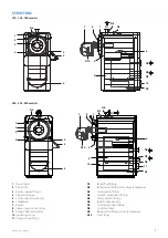
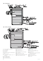
Page 7: ...Inspection plugs 5 Control panel accessory 6 Smokebox 7 Burner 8 Flame inspection window 9 Primary heat exchanger 10 Insulating casing 11 Flue gas drain fitting N1 Boiler flow fitting N2 Boiler return...

Page 8: ...ory 6 Smokebox 7 Burner 8 Flame inspection window 9 Primary heat exchanger 10 Insulating casing 11 Flue gas drain fitting N1 Boiler flow fitting N2 Boiler return fitting at medium temperature N3 Instr...

Page 9: ...TIONS 120 140 180 models N7 N4 N1 N6 N8 N3 N9 N2 N10 P2 L2 L1 P1 H1 H H2 c H12 H6 H10 H9 H8 L P5 P4 P3 P b N2 N9 N4 N7 250 320 420 models N3 N1 N6 N8 N10 L2 L1 P2 P1 H2 H1 H5 H4 H L P5 P4 P3 L6 N7 N4...

Page 10: ...0 690 690 800 800 800 920 920 920 920 L6 mm 150 150 150 200 200 200 200 P mm 1270 1587 1760 1765 2005 2300 2452 2452 2695 2695 P1 mm 851 1106 1106 1041 1281 1536 1560 1560 1810 1810 P2 mm 679 934 934...

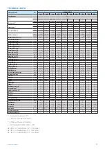
Page 11: ...83 210 97 271 25 376 73 482 22 632 90 836 34 1054 85 1175 40 1280 90 Maxfluegasflowrate kg h 175 52 204 73 263 28 365 65 468 01 614 33 811 75 1023 78 1140 89 1243 26 Minfluegasflowrate kg h 35 10 40 9...

Page 12: ...ol panel QETERM01CE eterm system control panel QETERM02 eterm Easy manager panel QCTETERM BURNERS The burners are supplied together with MONOLITE GT Boilers and are CE marked in accordance with Europe...

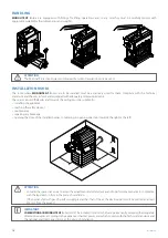
Page 13: ...T 3 SLATS 4 CONTROL PANEL 5 BURNER 6 flow ELBOW 7 and thermoceramic material for burner head 7 5 3 2 4 6 1 m IMPORTANT Upon receipt of MONOLITE GT Boiler make sure that the supply is intact and undama...

Page 14: ...ng the safety devices maintenance repairing any breakage opening the door of the installed burner considering its opening direction towards the right or the left 2 m 2 m 2m 2m a ATTENTION Consider the...

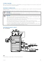
Page 15: ...he supply line does not exceed the operating pressure indicated on the plate del Gruppo Termico Make sure that the drains of the safety valves del Gruppo Termico and of the heater if any are connected...

Page 16: ...gauge 7 Condensate neutraliser see ICI catalogue 8 Pressure transducer 9 Pressure gauge tap 10 Shock absorbing pipe 11 Safety valve no 1 12 Manual shut off valve 13 Expansion vessel 14 Level probe glo...

Page 17: ...non insulated drain pipes can lead to a potential risk and the tightness of the joints must be ensured with materials resistant to the temperatures of the drain flue gases we recommend at least 250 C...

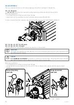
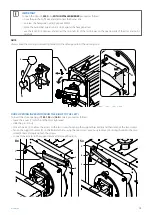
Page 18: ...780 850 models 250 320 420 555 700 780 models The door is factory set with a standard opening from the left LH to the right RH m IMPORTANT The hinges of the opening side must have the nut 1 loosened a...

Page 19: ...ring nuts well tightened on the side opposite to the opening one 6 4 5 DOOR OPENING INVERSION FROM THE RIGHT TO THE LEFT To invert the door opening of 120 140 and 180 models proceed as follows leave...

Page 20: ...en the nuts 3 Right hinge loosen the nuts 6 and disengage the conical washers 7 from the door mechanical tubes 8 DOOR ADJUSTMENT a DANGER Incorrect door adjustment with consequent damage to people and...

Page 21: ...and check that the distance between the appliance front plate and the door wall is the same on both sides If not with the door ajar loosen the locking nuts 4 of the hinge units work on ring nuts 5 to...

Page 22: ...using the supplied screws and nuts insert the slats 2 on the lateral and front side m IMPORTANT The panel supporting slat 5 must be the seventh one on the side featuring the control panel The cross b...

Page 23: ...and the door The strip must be wrapped around the combustion head for at least one entire circumference without having to fill the whole thickness of the gap 1 4 5 3 2 6 1 Burner 2 Flange 3 Gasket 4...

Page 24: ...Conformity of the system built m IMPORTANT It is mandatory to use an omnipolar thermal magnetic line circuit breaker complying with the Standards CEI EN contact opening of at least 3 mm observe the co...

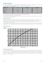
Page 25: ...e flame and thus to a significant reduction of the service life del Gruppo Termico Limestone gathers in the points where the wall temperature is higher and the best defence against it at the construct...

Page 26: ...arators once the air has been expelled bring the pressure back to the preset value and close the manual and or automatic supply tap After the initial filling it is necessary to prevent oxygen and untr...

Page 27: ...e on the ambient thermostat or chronothermostat and activate a heat request The Boiler will perform the ignition phase and will operate until the adjusted temperatures will be reached m IMPORTANT In c...

Page 28: ...ler is not used for a long period of time it is recommended to position the central panel switches and the control panel switch to OFF close the fuel and water interception valves of the hydraulic sys...

Page 29: ...h water mixed with denatured alcohol or specific non abrasive detergents Dry the surfaces thoroughly after cleaning Boiler internal cleaning To perform the internal cleaning disconnect from the burner...

Page 30: ...the tightness of boiler flue gas pipe and chimney Check the door tightness Gas smell Gas supply circuit Check sealing possible obstructions combustion quality Frequent safety valve triggering Excessi...

Page 31: ...a web page on which to register the data of your appliance and system by completing the indicated spaces Once registered authenticate your e mail address by clicking on the link that will be sent by e...

Page 32: ...I VR 02245640236 DECLARATION OF CONFORMITY WITH THE EUROPEAN COMMUNITY REGULATIONS I undersigned Emanuela Lucchini Managing Director of ICI CALDAIE S p A headquarted in via G Pascoli 38 37059 Campagno...

Page 33: ...Notes 33 6 Notes...

Page 34: ...Notes 34...

Page 35: ...Notes 35...

Page 36: ...ICI CALDAIE SpA 37059 Fraz Campagnola di Zevio Verona Italy Via G Pascoli 38 Phone 39 0458738511 Fax 39 0458731148 info icicaldaie com www icicaldaie com...

Reviews: