background image

Torus 126, 380 and 500


Operator Manual

2-8     Safety Warnings for  126, 380 and 500 Printers

Rev AB 


Warning

Do not point the printhead directly and in close proximity to the 
eyes, unless the printer is switched off and isolated from the mains 
and compressed air supplies.

Warning

The printer uses an operator control console mounted on the top of 
the unit. Ensure that this panel is at a height where access and use is 
least restricted.

Warning

Regard any warning or hazard information supplied with any 
cleaning fluid or consumable products. When using any chemicals, 
always wear protective gloves and only use in well-ventilated areas.

Warning

There will be sections of the 602004 Torus 126, 380 and 500 control 
board that will be permanently powered via the on-board lithium 
battery - therefore it is essential that the board should never be 
placed onto nor stored in or on any conductive surface (including 
conductive, plastic bags etc.) as this would flatten the battery and/or 
potentially result in battery overheating.

Warning

The Torus 126, 380 and 500 printer is supplied with warning 
symbols for power supply and compressed air. If any part of these 
symbols become damaged, worn or removed they must be 
immediately replaced.

Summary of Contents for Torus 126

Page 1: ...P N 361715 21 Revision AB November 2007 TORUS 126 380 500 Operator Manual...

Page 2: ...asICE All rights reserved This document is the property of Interactive Coding Equipment and contains confidential and proprietary information owned by ICE Any unauthorized copying use or disclosure o...

Page 3: ...o frequency energy and if not installed and used in accordance with the instruction manual may cause harmful interference to radio communications Operation of this equipment in a residential area is l...

Page 4: ...quipment est certifi CSA For Customers in the European Union This equipment displays the CE mark to indicate conformance to the following legislation EN60950 1 2001 A11 2004 Safety Requirements for I...

Page 5: ...mmitment The ICE Total Source Service Program is an integral part of our business in providing marks codes and images where when and how often customers specify for packages products or printed materi...

Page 6: ...For more information on Interactive Coding Equipment Customer Training Courses call 1 800 843 3610 within the United States only Outside the U S customer should contact a ICE subsidiary office or the...

Page 7: ...tion 2 1 Safety Conventions Used in the Manual 2 2 Warning Statements 2 2 Caution Statements 2 2 Equipment Safety Guidelines 2 3 Comply with Electrical Codes 2 3 Avoid Breathing Exhaust Vapors 2 3 Do...

Page 8: ...gh Quality Print 4 14 Clean the Printhead 4 15 Button A 4 16 Button B 4 17 Chapter 5 Software Operations Select a Job for Printing 5 1 Introduction 5 1 Variable Information 5 5 Introduction 5 5 How to...

Page 9: ...ation to the operator The Slave units do not have the interface An external PC is required only to configure the printer and download the messages into the printer The auto purging printhead makes sur...

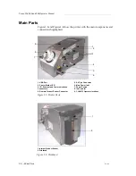
Page 10: ...connections highlighted Figure 1 1 Printer Parts 1 USB Port 2 Printer Status LED 3 I O Ethernet and Communications Connectors 4 Remote Product Sensor Connector 5 Air Pipe Connector 6 Main Power Inlet...

Page 11: ...nstall operate service or maintain this equipment Warning The intended use of this printer is to print information directly onto a product Use of this equipment in any other purpose may lead to seriou...

Page 12: ...ry or death They have a triangular symbol with an exclamation mark to the immediate left of the text They are always preceded by the word Warning They are always found before the step or information r...

Page 13: ...elines pertaining to the operation and handling of the printer and associated equipment Warning Always observe the following safety guidelines when operating and handling the printer and associated eq...

Page 14: ...e or obstruct any warning caution or instruction labels present on the printer Placement of the Printer Warning Do not place the printer in a hazardous location Hazardous locations might create an exp...

Page 15: ...fire Wear Safety Glasses Wear safety glasses with side shields or equivalent eye protection when handling any ink make up fluid or cleaning solution If it splashes on your eyes flush your eyes with wa...

Page 16: ...eference in case you need to consult a physician regarding an ink related accident Additional copies of MSDSs are available upon request and can be obtained by contacting the ICE Customer Service Depa...

Page 17: ...ith a locally positioned mains supply isolation device This can be either a plug and socket or a switch disconnector or circuit breaker in accordance with IEC 60947 3 or IEC 60947 2 Warning Always iso...

Page 18: ...uid or consumable products When using any chemicals always wear protective gloves and only use in well ventilated areas Warning There will be sections of the 602004 Torus 126 380 and 500 control board...

Page 19: ...Dispose the used batteries according to the local regulations Replace with the correct type of battery The failure to follow this warning can cause injury or explosion Medical Emergencies This sectio...

Page 20: ...ed in the United States If the bottle or MSDS cannot be located the physician can contact the Rocky Mountain Poison Control Center to obtain the information required Rocky Mountain Poison Control Cent...

Page 21: ...n The CLARiTY operator interface is a touch screen system The icons in the interface help the operator to navigate through the software easily Normally most areas of the interface are active The opera...

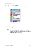
Page 22: ...Y The Home Page of the CLARITY is shown in Figure 3 1 Screen Description Icons The screen has icons that help you navigate to the key pages of the interface You can reach any key page from the current...

Page 23: ...is useful to find a Job in the Torus 126 380 and 500 database Control icons Refer to Control Icons on page 3 3 Job Use to load the next image job for printing and to enter any variable data Navigation...

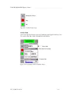
Page 24: ...The Production Performance and Consumables areas in Figure 3 4 take you to the screens that have more information and statistics Figure 3 3 Control Frame Icons Stop Run Start up Shut Down Figure 3 4 P...

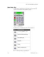
Page 25: ...phone style data entry pad is provided to the operator to enter the data in the CLARiTY interface The different keys in the data entry pad are shown in Table 3 2 Key Characters in turn 1 _ ABC2abc DE...

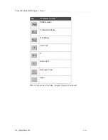
Page 26: ...380 and 500 Operator Manual 3 6 Data Entry Pad RevAB PQRS7pqrs TUV8tuv WXYZ9wxyz Cursor left 0 Cursor right Backspace Clear Space Key Characters in turn Table 3 2 Data Entry Pad Map English Default C...

Page 27: ...following tasks Turn on the printer Set the air pressure Start the printer Printer LED Functions Add the ink Get High quality print Clean the printhead Turn on the Printer Press the power switch on t...

Page 28: ...3 When the self diagnostic checks are complete the CLARiTY Home Page appears refer to Figure 4 2 4 The status window of the Home Page shows the SHUTDOWN status 5 During the SHUTDOWN status the Stop r...

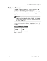
Page 29: ...control knob to the right side To decrease the pressure turn the knob to the left side Figure 4 3 on page 4 4 Caution The air pressure must be set according to the printer type Follow the recommended...

Page 30: ...Torus 126 380 and 500 Operator Manual 4 4 Set the Air Pressure RevAB Figure 4 3 Air Regulator Control Knob...

Page 31: ...the CLARiTY Home Page refer to Figure 4 4 The Stop and Run buttons become active Figure 4 4 If a fault or a warning condition exists a fault or warning message appears in the status window instead of...

Page 32: ...nsert a new ink canister The number of prints possible with the available ink Review the Ink Status The Consumables area of the Home Page screen displays a percentage value of ink that is left in the...

Page 33: ...mables meter status is red before a new canister is fitted the printer will go through a longer filling cycle before the printing continues Color Description Blue The reservoir is full and replacement...

Page 34: ...canister 1 Touch the Consumables area on the Home Page Figure 4 6 on page 4 7 The Consumables page appears Figure 4 7 2 Touch the Add Ink icon Figure 4 7 The Add Ink screen appears Figure 4 8 on page...

Page 35: ...canister code found on the label of the every ink canister Figure 4 9 on page 4 9 and touch the OK icon If you enter a wrong ink canister code an error message appears 4 10 Enter the correct ink cani...

Page 36: ...amage will not be covered under warranty 4 After the CLARiTY validates the new ink canister code you can replace the empty canister with a new canister To fit the new canister do the following tasks a...

Page 37: ...nister into the canister chute and turn to your right Figure 4 12 7 Insert and set the new canister inside the chute carefully Do not overtighten Note When you must refit a half full ink canister the...

Page 38: ...ber of prints Figure 4 14 on page 4 13 appears This screen displays Prints Per Ink Canister and Prints Left in Canister The Prints Per Ink Canister gives the number of prints from a full ink canister...

Page 39: ...Time and Estimated Time Remaining for the current ink canister Figure 4 15 on page 4 13 Figure 4 14 Number of Prints Prints from a full Prints Left from the Current Canister Ink Canister Figure 4 15 E...

Page 40: ...he image then an encoder must measure accurately the speed of the product This accuracy in the speed measurement leads to best print performance The maximum and minimum conveyor speeds for Torus 126 3...

Page 41: ...on the front side of the printer helps to protect the printhead from any potential damage and to maintain the jetting distance to the product Clean the Printhead The 126 380 500 printhead does not req...

Page 42: ...t has decreased and not acceptable standard You must press button A in this condition You can use the button for the following two purposes Press the button for one second then release to start the se...

Page 43: ...ink and dirt This method is best to remove any dirt following a visual inspection of the printhead Basic Maintenance When the printer is operated in dirty environments the operator must clean around...

Page 44: ...500 Operator Manual 4 18 Clean the Printhead RevAB Figure 4 19 Printhead Jetting Face 1 Printhead Nozzle Plate 2 Blow Nozzle Plate 3 Ink Collector 4 Knife Edge 5 Ink Drain Channel 6 Printhead Front P...

Page 45: ...troduction When the printer is in Running Offline or in the Shutdown status you can select a new print image or job You can select edit and see the image on the WYSIWYG display before printing the ima...

Page 46: ...Torus 126 380 and 500 Operator Manual 5 2 Select a Job for Printing RevAB Figure 5 1 Job Icon Job Home Figure 5 2 List of Jobs List of Jobs...

Page 47: ...A scroll bar appears Figure 5 4 on page 5 4 The scroll bar helps you move up and down the database to see all the jobs and select the required job Touch the Data Entry Pad icon Figure 5 4 on page 5 4...

Page 48: ...Torus 126 380 and 500 Operator Manual 5 4 Select a Job for Printing RevAB Figure 5 4 Scroll Bar Scroll Bar Data Entry Pad Figure 5 5 Job Selection Screens...

Page 49: ...e information fields like a Batch Code on the selected Job CLARiTY prompts to edit or enter these fields If there are any variable TEXT fields CLARiTY displays them first The check box at the side of...

Page 50: ...ob BBE1 and there is a DATE field variable only for use as a Best Before End Date How to Change Variable Information Do the following tasks to change the default data for the DATE field variable in th...

Page 51: ...ay of the month touch the date Note The red box in Figure 5 8 displays the current date and the blue background displays the date selected for printing The dates that are not available for selection a...

Page 52: ...screen Figure 5 10 Use the Zoom icon to see a bigger image 6 Check the Job for correct data and touch the OK icon The printer prints all the products with the new job information You can touch the OK...

Page 53: ...e job name on the screen and the WYSIWYG information of the job is displayed The example below displays the job that the 126 380 and 500 printer is printing The job is shown in the WYSIWYG display Fig...

Page 54: ...to Offline status Note If the print sensor is activated when the printer is in Offline status the printer will not operate Note If the print sensor is activated when the printer is in Online status th...

Page 55: ...Printhead setup page appears Figure 5 14 2 Touch the Registration Delay icon Enter the new print position in millimeters with the keypad Figure 5 15 Follow any of the below methods to make the adjustm...

Page 56: ...Torus 126 380 and 500 Operator Manual 5 12 Print Position Adjustment RevAB Figure 5 15 Registration Delay Registration Delay Data Entry Pad Figure 5 16 Registration Delay Keypad...

Page 57: ...ns the ink is returned to the ink reservoir and used again If the printer operates in a very dirty environment the self cleaning cycle must be performed more number of times This process maintains goo...

Page 58: ...nings and Fault Messages RevAB Warnings and Fault Messages When a Warning or a Fault condition occurs the CLARiTY displays the related message at the top of the screen Figure 5 19 Figure 5 18 Prints p...

Page 59: ...Warning condition the printer continues to operates When you touch the Warning message area on CLARiTY instructions to clear the message are displayed The Figure 5 20 shows the ink low warning and gi...

Page 60: ...ault status to the production line then the printer can stop the line The above interlock helps the customer to make sure that the printing is done on all the products Note The LED below the CLARiTY O...

Page 61: ...Torus 126 380 and 500 Operator Manual RevAB Warnings and Fault Messages 5 17 When the Fault message is cleared then the printer begins to print again Figure 5 22 Out of Ink Fault...

Page 62: ...igate to Tools Setup Control from the Home Page The Control Screen appears Figure 5 23 2 Select the Date and Time from the list displayed Figure 5 23 3 Touch Date and the calendar page appears Figure...

Page 63: ...ect Time and Date 5 19 7 Touch the Time icon and the time page appears Figure 5 25 8 Use the and keys to set the Hours Minutes and Seconds 9 Touch the OK button 10 Touch the Home icon to return to the...

Page 64: ...ry For example Month Day Year for USA and Day Month Year for UK Do the following tasks to select the language 1 Navigate to Tools Setup Control Internationalisation and the Internationalisation screen...

Page 65: ...K icon 4 Select the Region Country icon to select the region or the country Figure 5 26 on page 5 20 5 Select the region required Figure 5 28 and touch the OK icon 6 Touch the OK icon 7 Touch the Home...

Reviews: