ICC OPC-PRT3 Instruction Manual Download Page 48

ICC 


47 


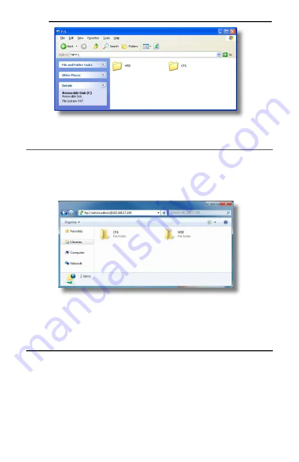
Figure 25: USB File Access via Windows Explorer 


8.3 

FTP with Windows Explorer 

To use FTP with Microsoft Windows Explorer, first open either 

“Windows Explorer” or “My Computer”. 

Please note that the indicated procedure, prompts and capabilities outlined here can vary depending on 
such factors as the installed operating system, firewalls and service packs. 
 
In the “Address” field, type in “ftp://admin:admin@” and then the IP address of the target interface card 
(if the user name and password have been changed from its default, then replace the first “admin” with 
the new user name and the second “admin” with the password.) Refer to Figure 26. 


Figure 26: FTP via Windows Explorer 

 
Note that the behavior of Windows Explorer FTP will vary from PC to PC. If you are having issues 
connecting FTP, there are other FTP client tools available such as Windows Command Prompt, Core 
FTP, FileZilla, SmartFTP etc. that can also be used to reliably 

access the card’s file system. 


8.4 

Loading New Web Server Content 

The interface card’s web server resides in the file system and can be updated in the field. This section 
will discuss how to update the web server.  
 
Besides the new “WEB” folder containing the new web server, the update requires a USB or FTP 
connection as described earlier in this section. To update the web server, complete the following steps: 

1. 

Navigate to the 

card’s file system (see section 8.2 or 8.3). 

2. 

Backup the “WEB” folder if desired by copying it to the local computer. 

3. 

Delete the “WEB” folder from the card’s file system. 

4. 

Copy the new “WEB” folder to the card’s file system. 

Summary of Contents for OPC-PRT3

Page 1: ...s of inverters to Ethernet communication networks Please read this instruction manual thoroughly in order to become familiar with the proper interface handling installation and usage procedures Improp...

Page 2: ...FE SUPPORT DEVICES OR SYSTEMS Life support devices or systems are devices or systems intended to sustain life and whose failure to perform when properly used in accordance with instructions for use pr...

Page 3: ...safety information and precautions before operating the inverter Safety precautions in this instruction manual are classified into the following two categories Failure to heed the information indicate...

Page 4: ...ling during installation or removal may cause equipment failure Do not subject the cables to scratches excessive stress heavy loads or pinching To prevent damage due to electrostatic discharge always...

Page 5: ...g so may cause electrical shock or injuries For clarity purposes illustrations in this manual may be drawn with covers or safety guards removed Ensure all covers and safety guards are properly install...

Page 6: ...lated Settings 23 3 2 Inverter Reaction to Network Timeout Conditions 24 4 FUNCTION CODE NUMBERING AND BEHAVIOR 25 4 1 Register Numbers 25 4 2 Scanned Function Codes 28 4 3 Commonly Used Function Code...

Page 7: ...gs 52 10 1 8 Holding Input Register Remap Settings 52 10 2 EtherNet IP 53 10 2 1 Overview 53 10 2 2 Server Settings 53 10 2 3 Connection Timeout Options 54 10 2 4 Generic Class 1 I O Produced and Cons...

Page 8: ...95 10 4 16 Multi state Value Object Settings 95 10 5 PROFINET IO 97 10 5 1 Overview 97 10 5 2 Device Settings 97 10 5 3 Connection Timeout Options 97 10 5 4 Cyclic I O Produced and Consumed Data Acce...

Page 9: ...afe place for future reference or unit inspection Note that different interface firmware versions may provide varying levels of support for the various protocols When using this manual therefore alway...

Page 10: ...all straight through and cross over cables Cable Type CAT5 type 8 conductor UTP patch cables Cable Length 100m per segment max Topologies Star Tree Linear Bus Daisy chain Ring DLR MRP Table 4 Modbus T...

Page 11: ...of Connections 16 Total for both Class 1 and Class 3 RPI Min 1ms I O Input Size Max 32 input words user configurable I O Output Size Max 32 output words user configurable Generic User Configurable Ass...

Page 12: ...ax Read Size 240 bytes 120 16 bit Integers Max Write Size 240 bytes 120 16 bit Integers Table 7 BACnet IP Specifications Item Description BACnet IP Annex J Protocol Revision 2 Standard Device Profile...

Page 13: ...nly 1 controller Table 9 Applicable Inverters Series Type Capacity ROM version FRENIC MEGA FRN G1 All capacities 1000 or higher FRENIC HVAC FRN AR1 All capacities 1100 or higher FRENIC HVAC P FRENIC A...

Page 14: ...rrect quantity of each item was received and that no damage occurred during shipment Some drives may require an additional option attachment or enclosure Contact Fuji OPC PRT3 interface board refer to...

Page 15: ...ated on the inverter s control board Refer to section 2 2 Inverter Control Board Connector Attaches to the inverter s connector board which may vary depending on the inverter model USB Port USB 2 0 po...

Page 16: ...tatus Note Off Device Off The inverter power is off Green Blink Red Blink Startup Startup blink sequence Green On Device On Normal status Green Blink Discovery identification PROFINET discovery and id...

Page 17: ...iring polarity indicators Only one additional option card may be used when the OPC PRT3 is installed in the inverter If two additional option cards are required please consult with the factory first t...

Page 18: ...face Card 4 Secure the interface card to the connector board PCB by first tightening the included M3 x 6mm screw into the inverter standoff located at the lower right hand corner of the interface card...

Page 19: ...nt or enclosure Contact Fuji 1 Remove the front cover from the inverter to expose the control printed circuit board control PCB Install the interface card according to the inverter capacity as shown i...

Page 20: ...ICC 19 Figure 7 Installation for 15 kW and Smaller Inverters Interface Card Connector Board Option Case...

Page 21: ...ICC 20 Figure 8 Installation for 18 5 kW to 22 kW Inverters Interface Card Connector Board Option Case...

Page 22: ...ailure 3 Secure the interface card to the connector board PCB by first tightening the included M3 x 6mm screw into the inverter standoff located at the lower right hand corner of the interface card Ne...

Page 23: ...as the inverter s input power or motor wires 5 Reinstall all covers removed in step 1 Take a moment to confirm that the Ethernet cables are not being pinched and are not routed near any power carrying...

Page 24: ...de Selection y98 If the inverter is to be controlled from the network then set the value of y98 to 3 fieldbus option A setting of 3 for y98 may also be appropriate even if H30 is configured for an alt...

Page 25: ...ed within the time specified by o28 ignore the communications error After the timeout coast to a stop and trip er5 3 13 to 15 Maintain present operation ignoring the communications error no er5 trip 1...

Page 26: ...function code E05 for example is 5 To determine the register number for a given function code therefore the group number is first multiplied by 256 then added to the offset number plus 1 This operatio...

Page 27: ...0 1 769 P03 motor 1 rated current 3 x 256 3 1 772 P99 3 x 256 99 1 868 H High Performance Functions 4 H00 4 x 256 0 1 1025 H11 deceleration mode 4 x 256 11 1 1036 H99 4 x 256 99 1 1124 A Motor 2 Para...

Page 28: ...rm Data 1 16 X00 alarm history latest 16 x 256 0 1 4097 X99 16 x 256 99 1 4196 Z Alarm Data 2 17 Z00 17 x 256 0 1 4353 Z53 3rd last alarm torque 17 x 256 53 1 4406 Z99 17 x 256 99 1 4452 b Motor 3 Par...

Page 29: ...interface card s internal memory Only those function codes selected in the Manage Device Parameters configuration windows in the Configuration Studio refer to section 6 8 will represent meaningful val...

Page 30: ...nly Used Function Codes For a complete listing of all available function codes their bit mappings scaling values etc please refer to the applicable inverter Instruction Manual and the Fuji RS 485 User...

Page 31: ...ICC 30 Table 16 Structure of Operation status Function code M14 Table 17 Structure of Rotation Speed Function code W08...

Page 32: ...fail safe values to any inverter function codes when a timeout event is triggered Refer to section 6 6 1 for details on how to configure fail safe values Figure 10 Timeout Processing Diagram Figure 10...

Page 33: ...ng the Device Configurations list heading and then Double clicking on the device in the Available Devices panel Right clicking on the device in the Available Devices panel and choosing Add from the co...

Page 34: ...d choosing Remove from the context sensitive menu Selecting Remove Selected Item from the Edit menu when the device is selected Clicking on the Remove button in the toolbar when the device is selected...

Page 35: ...roject panel select a parent object to display a summary of all its child objects For example selecting a protocol driver will display the driver s configuration in the Summary panel and list of curre...

Page 36: ...tion Each device added to a project can be individually tagged with a unique description string of up to 32 characters in length This allows the devices within a project or an automation system to be...

Page 37: ...tch Update Log After the studio has updated a card while in batch update mode a log is available that can be accessed by selecting Open Batch Update Log from the Help menu The log details the actions...

Page 38: ...a timeout event is triggered by a protocol the timeout objects are parsed and written to the corresponding function code s The timeout object s will be executed sequentially from first to last To add...

Page 39: ...settings during troubleshooting and add the studio as a program exception to the firewall configuration if necessary It may be necessary to restart your PC before the new firewall configuration can ta...

Page 40: ...ate IP addresses and are not directly accessible from the internet The router must be configured for port forwarding to map publicly accessible ports to private IP address and port combinations This i...

Page 41: ...ers that are accessed more frequently or require a faster update rate should be set to high priority All other parameters should be set to low priority The parameter list serves as a useful reference...

Page 42: ...can be backed up from the inverter and restored to the inverter refer to Figure 19 and Figure 20 This allows for easy inverter cloning The backup parameter values are stored as a CSV file A parameter...

Page 43: ...ns and configurations Please backup the configuration before executing this feature The factory settings can be restored by Right clicking on the device in the Project panel and choosing Restore Facto...

Page 44: ...r to 6 8 and must not be removed as it contains the definition of all available parameters not only for active web server content but also for the interface card itself All other files in the WEB fold...

Page 45: ...n loads the active content which initiates communication with the server Server Device Content is loaded onto server device s file system for web server 2 Active web content is delivered to client XML...

Page 46: ...it hexadecimal value e g 1F4 for a decimal value of 500 write_data Yes load_file Yes The absolute file path must start with a forward slash store_file Yes reinit No Reinitializes only the configurable...

Page 47: ...on the interface card s file system in the same manner as though they were traditional files stored on a local or remote PC Note that the USB and FTP connection will prevent the file system from being...

Page 48: ...behavior of Windows Explorer FTP will vary from PC to PC If you are having issues connecting FTP there are other FTP client tools available such as Windows Command Prompt Core FTP FileZilla SmartFTP...

Page 49: ...re apply those modifications using the Manage Device Parameters refer to section 6 8 Please consult technical support for any questions related to customized versions of param xml 6 Power cycle or re...

Page 50: ...e sure to read the firmware release notes and updated user s manual for any important notices behavior precautions or configuration requirements prior to updating your firmware 4 Ensure that the devic...

Page 51: ...ultiple registers 0 4 Read input registers 1 5 Write coil 1 6 Write single register 1 8 Diagnostics subfunction 0 only 15 Force multiple coils 2 16 Write multiple registers 0 10 1 4 Holding Input Regi...

Page 52: ...coil 34 targets is 34 1 16 1 as 33 16 mod 2 r1 1 Therefore reading coil 34 will return the value of register 3 bit 1 10 1 6 Connection Timeout Options In the studio s Project panel navigate to OPC PRT...

Page 53: ...bus transactions This may be especially true in situations where it is desired to access certain function codes that are non contiguous For example if it were desired to read the inverter s output fre...

Page 54: ...t Supports DLR Device Level Ring node Supports unconnected messages UCMM and up to 16 simultaneous class 1 I O or class 3 explicit connections Class 1 implicit I O supports both multicast and point to...

Page 55: ...on codes o27 and o28 which may result in an Er5 fault Refer to section 3 2 Enable Drive Fault Reset This will clear the Er5 fault once communication is re established This option is only available if...

Page 56: ...6 AC DC Drive Profile Class 1 I O Connection Access The interface card supports the ODVA AC DC drive profile No special EtherNet IP configuration of the interface card is required when using the AC D...

Page 57: ...Reset Inverter reset command 0 no action 0 1 rising edge reset Maps to inverter function code S06 bit 15 function code S06 operation command word RST bit NetCtrl Not used value is ignored NetRef Not...

Page 58: ...the current state of the Control Supervisor Object state machine Refer to the ODVA EtherNet IP specification object library for detailed information on the Control Supervisor Object state machine Spee...

Page 59: ...epresentation of the function code itself Tag names are generated according to the following structure function code group function code offset Where function code group is a 1 to 2 character field an...

Page 60: ...a name we will use EIP and an IP address deselect Open Module Properties and click OK 8 Download the configuration 9 Switch to online mode Right click on the 1756 ENBT A module in the I O Configuratio...

Page 61: ...he ControlLogix PLC Once an I O connection is established it is automatically synchronized at an interval defined by the Requested Packet Interval RPI 1 Register the interface card s EDS file In the m...

Page 62: ...Right click on the 1756 ENBT A node under the I O Configuration in the controller organizer view and choose New Module 11 Find the interface card in the Select Module dialog box as shown in Figure 31...

Page 63: ...see the interface card in the 1756 ENBT A branch under the I O Configuration in the controller organizer view The full I O Configuration tree should appear similar to Figure 34 Figure 34 AOP Interfac...

Page 64: ...e project to the PLC Verify that the newly added inverter is available and operating correctly by observing any indications shown on the inverter s icon When the inverter s icon is selected its status...

Page 65: ...onfirm that the interface card s Network Status LED should be solid green indicating an online connected state 5 By double clicking Controller Tags in the project tree it is possible to view the newly...

Page 66: ...I O Configuration in the controller organizer view and choose New Module 3 Choose Generic Ethernet Module in the Select Module dialog box and click Create Refer to Figure 37 Figure 37 Adding a New Ge...

Page 67: ...t consumed data word configuration with two relevant function codes S06 and S05 We therefore set the Output Size to 2 Configuration The Configuration Assembly Instance is unused and its instance numbe...

Page 68: ...ode S06 which is the inverter s command register A value of 0x0001 therefore means that the FWD run forward bit has been turned ON Similarly we can see that the second 16 bit word of output data Inter...

Page 69: ...Double click MainRoutine under Tasks MainTask MainProgram in the controller organizer view 6 Right click on the first ladder logic rung in the MainRoutine window and select Add Ladder Element 7 The Ad...

Page 70: ...the steps in section 10 2 11 Please note that the Assembly Input Instance must be changed to 71 and the Assembly Output Instance must be changed to 21 Refer to Figure 47 Figure 47 AC DC Drive Profile...

Page 71: ...Right click on the first ladder logic rung in the MainRoutine window and select Add Ladder Element 7 The Add Ladder Element window appears 8 Select the AC DC drive profile add on instruction in the Ad...

Page 72: ...ICC 71 Figure 51 Configure AC DC Drive Profile AOI 11 The program is now complete 12 Save download and run the program...

Page 73: ...quest if a connection failure occurs f Collapse the connection tag again by clicking on the sign next to the tag name g Select the Edit Tags tab again Create another new tag by entering data_array in...

Page 74: ...ion The Message Configuration window will open Refer to Figure 56 Figure 56 MSG Instruction Configuration c Configuration tab settings i Change the Message Type to CIP Data Table Read ii In the Source...

Page 75: ...smission If disabled unchecked the connection is opened before and closed after every transmission For efficiency it is recommended to enable Cache Connections e Click OK to close the MSG Configuratio...

Page 76: ...e function codes being read from the interface card double click Controller Tags in the controller organizer view b Select the Monitor Tags tab and expand the data_array tag c 21 function code values...

Page 77: ...lly be replaced in an actual application program by user provided logic that controls the conditions under which write operations would be performed Figure 61 Reading and Writing via MSG Instructions...

Page 78: ...by the limitations of the programming software but is a value of 13668 max Refer to section 4 1 for the function code to register mapping Table 29 provides some examples of various combinations of fi...

Page 79: ...on Array Max Number of Accessible Elements N60 0 N60 0 1st 32 N60 N60 15 N60 15 16th 16 N60 N60 31 N60 31 32nd 1 The application PLC program uses a MSG instruction that is configured with a Data Table...

Page 80: ...functionality of the MSG instruction which will perform the data read c Follow the same procedure to create a data file This file will be used to store the incoming data read from the interface card E...

Page 81: ...onfigure the MSG instruction a Set the Read Write field to Read Target Device field to PLC5 Local Remote field to Local and Control Block to N20 0 b Upon hitting the ENTER key while in the Control Blo...

Page 82: ...set the Channel field to 1 Ethernet d Under Target Device set the Data Table Address field to N30 50 starting target register 2050 and set the MultiHop field to Yes to cause the MultiHop tab to appea...

Page 83: ...gering the MSG instruction at a specific rate or under specific conditions 7 The program is now complete Refer to Figure 70 Figure 70 Completed PLC Program 8 Save download and run the program a To vie...

Page 84: ...ICC 83 Figure 71 Monitoring the Data Being Read from the Inverter...

Page 85: ...e Figure 72 shows an example of two MSG instructions one for reading and one for writing It is evident from this logic that N20 and N21 are the two independent message control files created for these...

Page 86: ...net Application Specific Controller B ASC BACnet Smart Sensor B SS BACnet Smart Actuator B SA BACnet Interoperability Building Blocks Supported Annex K Data Sharing ReadProperty B DS RP B Data Sharing...

Page 87: ...the gateway supports N A Datatypes Supported The following table summarizes the datatypes that are accepted in the case of a write property service and returned in the case of a read property service...

Page 88: ...mentation Support R APDU Timeout R Number APDU Retries R Device Address Binding R Database Revision R R readable using BACnet services W readable and writable using BACnet services Table 32 BACnet Bin...

Page 89: ...ault R R R readable using BACnet services W readable and writable using BACnet services Table 34 BACnet Multi state Object Types Properties Supported Property Object Type Multi state Input Multi state...

Page 90: ...n off BI12 ALARM Alarm on off BI13 COMM_ESTABLISHED Communications established on off BI14 BUSY_WRITING Busy writing on off Table 36 Binary Output Object Instance Summary Instance ID Object Name Descr...

Page 91: ...dicates deceleration Corresponds to function code M14 bit 10 BI12 Indicates alarm Corresponds to function code M14 bit 11 BI13 Indicates communications established Corresponds to function code M14 bit...

Page 92: ...et for each device residing on a BACnet network Device Name Defines the node s name The device name must be unique across the entire BACnet network Enter a string of between 1 and 32 characters in len...

Page 93: ...ined by the BACnet Specification Relinquish Default Defines the default value to be used for an object s present value property when all entries in the object s priority array are NULL 10 4 10 Analog...

Page 94: ...object s Polarity is set to Reverse Active Text Specifies the description of the object s active state Enter a string of up to 32 characters in length This field is optional and may be left blank Inac...

Page 95: ...everse from this dropdown menu For further detail refer to the Bitmask behavioral description Relinquish Default Defines the default value to be used for an object s present value property when all en...

Page 96: ...value will access Data Type Fixed at 16 Bit Unsigned 10 4 15 Multi state Output Object Settings Object Name The name of the BACnet object Enter a string of between 1 and 32 characters in length All o...

Page 97: ...ICC 96 Relinquish Default Defines the default value to be used for an object s present value property when all entries in the object s priority array are NULL...

Page 98: ...s Project panel navigate to OPC PRT3 Ethernet PROFINET IO Device Name The device name station name must be unique across the entire PROFINET network because it is used by controllers to uniquely ident...

Page 99: ...a produce word offset is not defined the value will default to 0 The size of the actual I O produced and consumed data is determined by the PROFINET controller The I O data format is summarized in Tab...

Page 100: ...type 3 Supports only Speed Control Mode 10 5 5 1 PROFIdrive Standard Telegram 1 The standard telegram 1 mapping is described in Table 41 Table 41 Standard Telegram 1 IO Data Word Offset Setpoint PLC t...

Page 101: ...FF3 active 6 1 Switch ON Inhibited Not ready to run command ON 0 Switch ON Not Inhibited Ready to run command ON 7 Not Used 8 1 Speed Within Tolerance Actual value equals the reference value and is wi...

Page 102: ...ate operating speed actual normalized Frequency Max 0x4000 x Speed Running NIST_A Equation 9 The Max Frequency term which appears in Equation 8 and Equation 9 is obtained from the setting of inverter...

Page 103: ...egister number described in section 4 1 The length is specified according to the number of bytes to access Since each register corresponds to 2 bytes of data the length must be an even number 10 5 7 T...

Page 104: ...will update the Hardware catalog Locate the device in the Hardware catalog In the Project tree double click on Device networks Select the Network view tab and locate the device in the Hardware catalog...

Page 105: ...s will assign the device to the PROFINET IO system as shown in Figure 80 Figure 80 PROFINET IO System 10 5 7 4 Assign IO Module Click on the device and then click on the Device view tab In the Hardwar...

Page 106: ...1 node Assign a unique and compatible IP address for this device as shown in Figure 82 Figure 82 Assign Unique Compatible IP Address Assign a unique PROFINET device name as shown in Figure 83 Figure 8...

Page 107: ...C interface and click the Start search button to discover and display the PROFINET devices on the network as shown in Figure 85 Select the device and click the Apply button Figure 85 Discover PROFINET...

Page 108: ...5 8 GE Proficy Configuration Example The following example will use GE Proficy Machine Edition SIM11 to demonstrate the basic procedure for configuring a PROFINET device The example will not cover al...

Page 109: ...he GSDML file Click the Open button to register the GSDML as shown in Figure 90 It is recommended to use the latest GSDML which is available via the product web page on the internet Figure 90 Register...

Page 110: ...vice Catalog and click the OK button as shown in Figure 91 The device is added under the Profinet Controller node as shown in Figure 92 Figure 92 Added Device to Configuration 10 5 8 3 Assign IO Modul...

Page 111: ...or your application Click the OK button as shown in Figure 94 Figure 94 Add IO Module The module will be reflected in the Navigator panel under the device as shown in Figure 95 Figure 95 Added IO Modu...

Page 112: ...que and compatible IP Address For this example the IP Address is set to 192 168 17 102 The resulting properties are shown in Figure 97 10 5 8 5 Save the Configuration The device configuration is now c...

Page 113: ...d and connected to the local Ethernet network Ensure that the card is programmed with compatible network settings Consult with your network administrator to determine the compatible settings Confirm t...

Page 114: ...m Adobe Flash Player is no longer supported Use the Configuration Studio Studio cannot discover the card The studio does not display the card under Online Devices Confirm that the card is running norm...

Page 115: ...ICC INDUSTRIAL CONTROL COMMUNICATIONS INC 230 Horizon Drive Suite 100 Verona WI 53593 USA Tel 1 608 831 1255 http www iccdesigns com...

Reviews: