background image


15 

Appendix Toxic or Hazardous Materials or Elements 

Component 

Name 

Toxic or Hazardous Materials or Elements 

Pb 

Hg 

Cd 

Cr VI 

PBB 

PBDE 

Circuit Board 

Component 

○ 

○ 

○ 

○ 

○ 

○ 

Device Case 

○ 

○ 

○ 

○ 

○ 

○ 

Wire and Cable 

○ 

○ 

○ 

○ 

○ 

○ 

Packing 

Components 

○ 

○ 

○ 

○ 

○ 

○ 

Accessories 

○ 

○ 

○ 

○ 

○ 

○ 


O: Indicates that the concentration of the hazardous substance in all homogeneous materials in the 

parts is below the relevant threshold of the SJ/T11363-2006 standard. 


X: Indicates that the concentration of the hazardous substance of at least one of all homogeneous 

materials in the parts is above the relevant threshold of the SJ/T11363-2006 standard. During the 

environmental-friendly use period (EFUP) period, the toxic or hazardous substance or elements 

contained in products will not leak or mutate so that the use of these (substances or elements) will not 

result in any severe environmental pollution, any bodily injury or damage to any assets.  The consumer 

is not authorized to process such kind of substances or elements, please return to the corresponding 

local authorities to process according to your local government statutes. 


Note 


This user

’s manual is for reference only. Slight difference may be found in user interface. 


All the designs and software here are subject to change without prior written notice. 


All trademarks and registered trademarks mentioned are the properties of their respective  

owners. 


If there is any uncertainty or controversy, please refer to the final explanation of us. 


Please visit our website for more information. 


Summary of Contents for ICIP D2010IR

Page 1: ...HD IR Vandal Proof Network Dome Camera User s Manual Version 1 2 2...

Page 2: ...r Network camera This user s manual is designed to be a reference tool for your system Please read the following safeguard and warnings carefully before you use this series product Please keep this us...

Page 3: ...n Please install the proper power cut off device during the installation connection Always follow the instruction guide the manufacturer recommended 4 Qualified engineers needed All the examination an...

Page 4: ...al component do not touch the enclosure when you are installing the device or clean the enclosure when you are doing maintenance work Please use professional optical clean method to clean the enclosur...

Page 5: ...ture 4 2 1 Components 4 2 2 Framework and Dimension 4 3 Device Installation 7 3 1 Installation Steps 7 4 Quick Configuration Tool 10 4 1 Overview 10 4 2 Operation 10 5 Web Operation 12 5 1 Network Con...

Page 6: ...rver backup function in accordance with your configuration and setup in alarm or schedule setting Support record via Web and the recorded file are storage in the client end PC Support network storage...

Page 7: ...r and is valid only when exposure mode is auto with range 1 100 Exposure Mode Manual Low noise Low motion blur Auto It ranges from 1 3 to 1 100000 Video Compression Standard H 264 H 264H MJPEG Video F...

Page 8: ...Port 10 100 Base T Ethernet Network Protocol Standard HTTP TCP IP ARP IGMP ICMP RTSP RTP UDP RTCP SMTP FTP DHCP DNS DDNS PPPOE UPNP NTP Bonjour SNMP QoS 802 1x Platform Standard PSIA ONVIF Remote Oper...

Page 9: ...ormation 2 2 Framework and Dimension Please refer to the following two figures for dimension information The unit is mm See Figure 2 2 to Figure 2 4 Component Component Name Component 1 Dome body Comp...

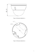
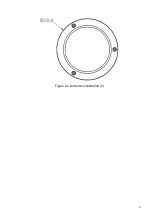
Page 10: ...5 Figure 2 2 Dimension illustration 1 Figure 2 3 Dimension illustration 2...

Page 11: ...6 Figure 2 4 Dimension illustration 3...

Page 12: ...urface according to the installation position map If user pulls out cable from side of cable channel it must go through the U shape channel on dome pedestal and take out cable from the side exit hole...

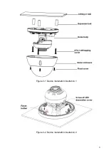
Page 13: ...8 Figure 3 1 Device installation illustration 1 Figure 3 2 Device installation illustration 2...

Page 14: ...e Reset button in Figure 3 2 for 1 to 2 seconds while connecting device to power then press WPS button on the router Generally the device can be connected to corresponding router within 1 minute suppo...

Page 15: ...n interface Figure 4 2 Search interface If you want to modify the device IP address without logging in the device web interface you can go to the configuration tool main interface to set In the config...

Page 16: ...uration tool main interface is shown as below See Figure 4 4 Figure 4 4 Main interface For detailed information and operation instruction of the quick configuration tool please refer to the Quick Conf...

Page 17: ...the PC and the network camera respectively Network camera default IP address is 192 168 1 108 Subnet mask is 255 255 255 0 Gateway is 192 168 1 1 Use order ping network camera address to check connect...

Page 18: ...gin After you successfully logged in please install WEB plug in unit Please refer to the Web Operation Manual included in the resource CD for detailed operation instruction See Figure 5 3 Figure 5 3 W...

Page 19: ...r Network connection error occurred Invalid network setup Invalid user name or password I can not play the download file There is no player There is no DX8 1 or higher For the MEDIA PLAYER there shall...

Page 20: ...toxic or hazardous substance or elements contained in products will not leak or mutate so that the use of these substances or elements will not result in any severe environmental pollution any bodily...

Reviews: