


Table 13. System board (continued)
No.
Connector/feature
Internal cable required
5
Memory module connector
None. Integrated
6
Docking-station connector
None. Integrated
7
ac power connector
None. Integrated
8
LCD connector
LCD cable assembly, connects to the Windows button
board, LCD module, ThinkPad logo LED (on the
A-cover), and ambient light sensor card
9
22
USB 3.0 connector
None. Integrated
10
Thermal fan connector
Thermal fan assembly with cable
11
Mini DisplayPort connector
None. Integrated
12
USB 3.0 Always-on connector
None. Integrated
13
Internal battery connector
Battery with cable
14
TrackPad connector
TrackPad cable (contained in the base cover
miscellaneous kit), connects to the trackpad assembly
15
Media-card reader
None. Integrated
16
Hard disk drive/buttons card connector
Hard disk drive/buttons cable (buttons include
the power button, volume-control buttons, and
screen-rotation-lock button)
17
WWAN card connector
WWAN card connects directly to the system board.
18
Speaker connectors
Speaker assemblies with cable
19
Fingerprint reader connector
Fingerprint reader cable (contained in the base cover
miscellaneous kit), connects to the fingerprint reader
assembly)
20
Wireless-LAN card connector
None. Card connects directly to the system board
21
Audio connector
None. Integrated
23
Micro-SIM-card slot
Micro SIM card
24
Ethernet connector
None. Integrated
25
HDMI connector
None. Integrated
26
27
Keyboard connector
Keyboard assembly with cables
Camera/microphone card connector and cable
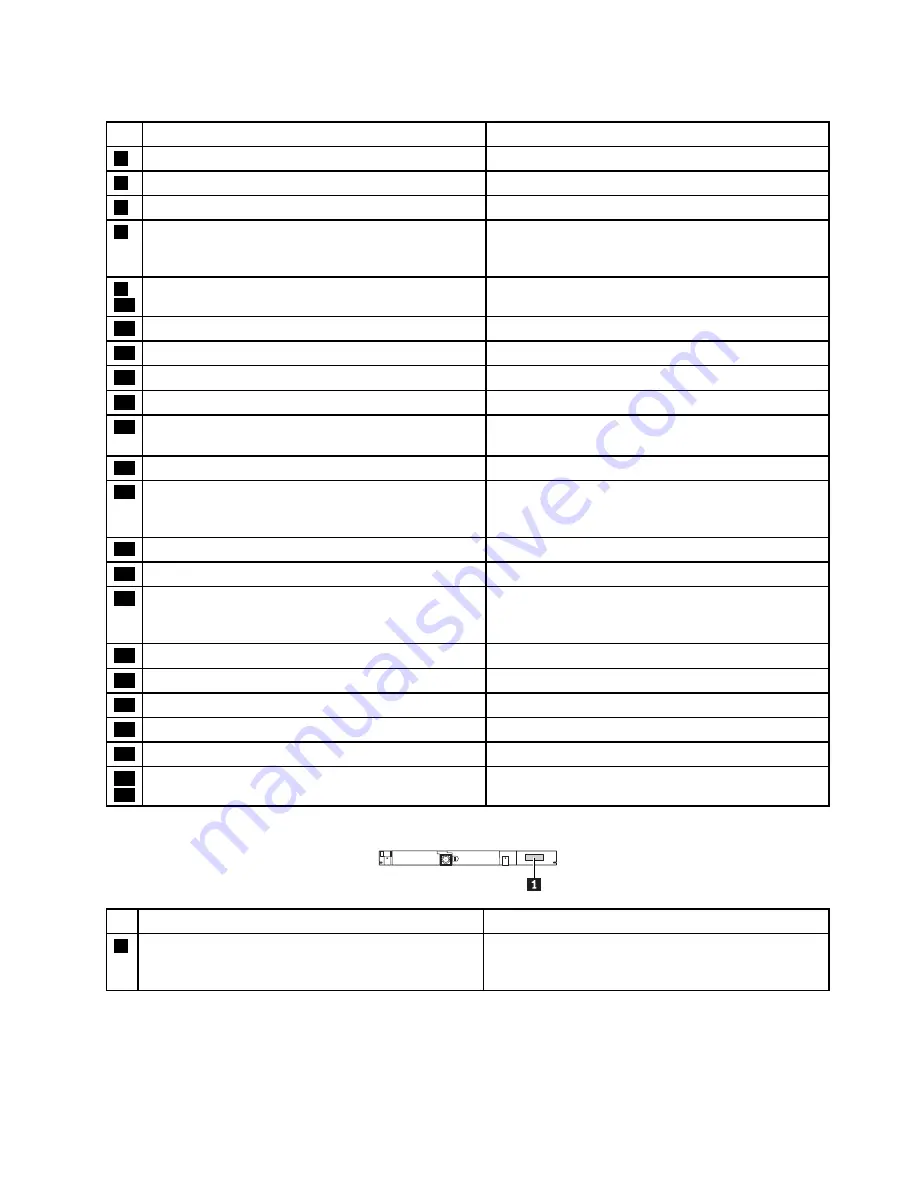
No. Connector/feature
Internal cable required
1
Camera/microphone card connector (internal)
Camera/microphone cable or
camera/digitizer/microphone cable, connects to the
system board
Chapter 7
.
Locations
53
Summary of Contents for YhinkPad T460
Page 1: ...Hardware Maintenance Manual ThinkPad T460 ...
Page 6: ...iv Hardware Maintenance Manual ...
Page 11: ...DANGER DANGER DANGER DANGER DANGER Chapter 1 Safety information 5 ...
Page 12: ...6 Hardware Maintenance Manual ...
Page 13: ...PERIGO PERIGO PERIGO PERIGO Chapter 1 Safety information 7 ...
Page 14: ...PERIGO PERIGO PERIGO PERIGO DANGER 8 Hardware Maintenance Manual ...
Page 15: ...DANGER DANGER DANGER DANGER DANGER DANGER Chapter 1 Safety information 9 ...
Page 16: ...DANGER VORSICHT VORSICHT VORSICHT VORSICHT 10 Hardware Maintenance Manual ...
Page 17: ...VORSICHT VORSICHT VORSICHT VORSICHT Chapter 1 Safety information 11 ...
Page 18: ...12 Hardware Maintenance Manual ...
Page 19: ...Chapter 1 Safety information 13 ...
Page 20: ...14 Hardware Maintenance Manual ...
Page 21: ...Chapter 1 Safety information 15 ...
Page 22: ...16 Hardware Maintenance Manual ...
Page 23: ...Chapter 1 Safety information 17 ...
Page 24: ...18 Hardware Maintenance Manual ...
Page 28: ...22 Hardware Maintenance Manual ...
Page 46: ...40 Hardware Maintenance Manual ...
Page 50: ...44 Hardware Maintenance Manual ...
Page 56: ...LCD FRUs 2 1 2 2 2 3 2 4 2 5 2 6 7 8 7 7 7 9 50 Hardware Maintenance Manual ...
Page 62: ...56 Hardware Maintenance Manual ...
Page 89: ...b c a Removal steps of the system board Chapter 9 Removing or replacing a FRU 83 ...
Page 107: ......
Page 108: ...Part Number SP40K04896 Printed in China 1P P N SP40K04896 1PSP40K04896 ...


