background image

6.


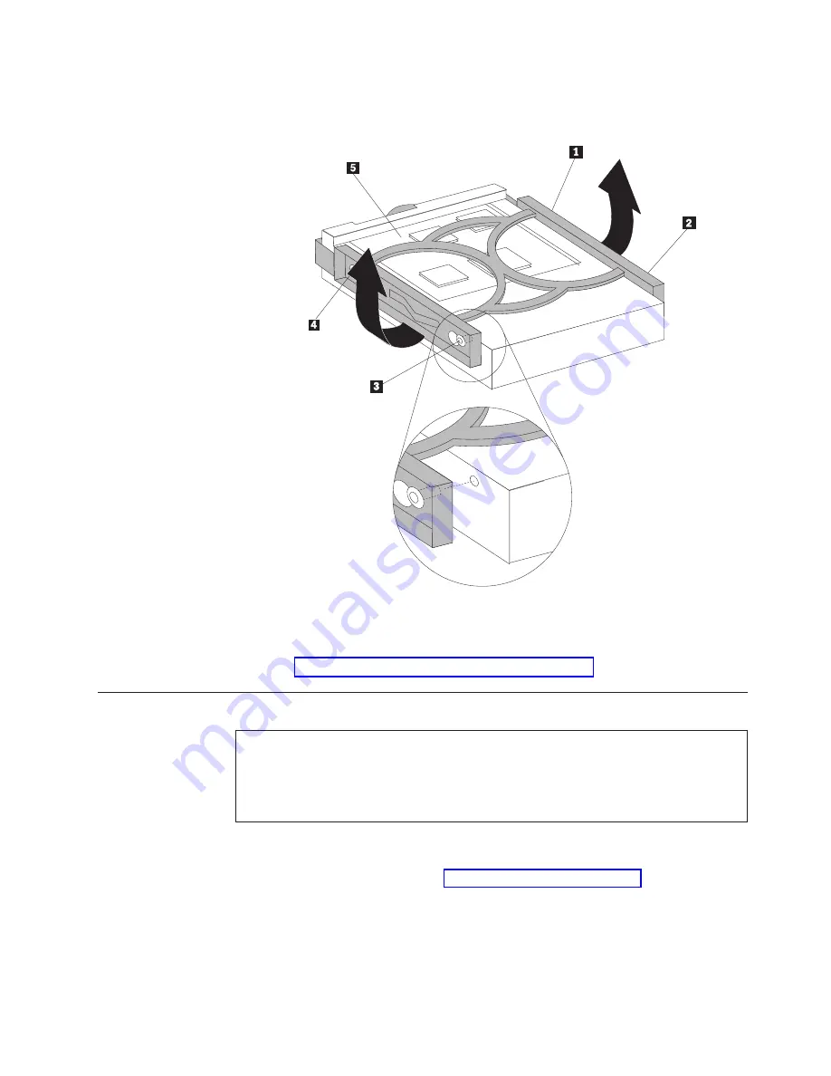
To


install


the


new


hard


disk


drive


into


the


blue


bracket,


flex


the


bracket


and


align


the


pins


1


through


4


on


the


bracket


with


the


holes


in


the


hard


disk


drive.


Do


not


touch


the


circuit


board


5


on


the


bottom


of


the


hard


disk


drive.


7.


Insert


the


new


hard


disk


drive


into


the


hard


drive


bay


until


it


snaps


into


position.


8.


Connect


the


signal


and


power


cables


to


the


rear


of


the


hard


disk


drive.


9.


Go


to


“Completing


the


parts


replacement”


on


page


26.

Replacing


the


optical


drive


Attention


Do


not


open


your


computer


or


attempt


any


repair


before


reading


the


“Important


safety


information”


in


the


Quick


Reference


that


was


included


with


your


computer


or


in


the


Hardware


Maintenance


Manual


(HMM)


for


the


computer.


To


obtain


copies


of


the


Quick


Reference


or


HMM

,


go


to


http://www.ibm.com/pc/support/.


This


section


provides


instructions


on


how


to


replace


an


optical


drive.


1.


Open


the


computer


cover.


See


“Opening


the


cover”


on


page


5.


Chapter


2.


Replacing


hardware


19

Summary of Contents for ThinkCentre 8104

Page 1: ...ThinkCentre Hardware Replacement Guide Types 8104 8105 8106 8107 Types 8108 8109 8117 8118 Types 8119 8120 8121...

Page 2: ......

Page 3: ...ThinkCentre Hardware Replacement Guide Types 8104 8105 8106 8107 Types 8108 8109 8117 8118 Types 8119 8120 8121...

Page 4: ...April 2005 Copyright International Business Machines Corporation 2005 All rights reserved US Government Users Restricted Rights Use duplication or disclosure restricted by GSA ADP Schedule Contract w...

Page 5: ...2 Locating components 3 Identifying parts on the system board 4 Chapter 2 Replacing hardware 5 Opening the cover 5 Replacing the power supply 6 Replacing the system board 8 Replacing the microprocess...

Page 6: ...iv Hardware Replacement Guide...

Page 7: ...ty information for replacing CRUs Do not open your computer or attempt any repair before reading the Important safety information in the Quick Reference that was included with your computer To obtain...

Page 8: ...se static electricity to build up around you v Always handle parts and other computer components carefully Handle adapters memory modules system boards and microprocessors by the edges Never touch any...

Page 9: ...f the computer To open the computer cover see Opening the cover on page 5 Locating the connectors on the front of your computer The following illustration shows the location of connectors on the front...

Page 10: ...pter connector 8 Ethernet connector 2 Integrated cable lock 9 USB connectors 3 Standard mouse connector 10 Audio line out connector 4 Standard keyboard connector 11 Audio line in connector 5 VGA monit...

Page 11: ...on will help you locate the various components in your computer 1 PCI riser 5 Hard disk drive 2 Power supply assembly 6 Internal speaker 3 Optical drive eject button 7 Cable clip 4 Optical drive 8 Rea...

Page 12: ...the system board 1 SATA connector 9 Internal speaker connector 2 IDE connector 10 Memory connector 1 3 PCI riser connector 11 Memory connector 2 4 Front panel connector 12 Microprocessor fan connecto...

Page 13: ...o 5 minutes to let the computer cool before opening the computer cover To open the computer cover 1 Remove any media diskettes CDs or tapes from the drives shut down your operating system and turn off...

Page 14: ...To obtain copies of the Quick Reference or HMM go to http www ibm com pc support This section provides instructions on how to replace the power supply 1 Open the computer cover See Opening the cover o...

Page 15: ...hassis so that the screw holes in the power supply assembly align with those in the chassis Note Use only the screws that are provided 9 Install and tighten the three screws at the rear of the chassis...

Page 16: ...a PCI adapter on page 22 4 Locate the rear fan bracket assembly and the rear fan connector See Locating components on page 3 and Identifying parts on the system board on page 4 5 Disconnect the rear...

Page 17: ...ace the heat sink on its side on a clean flat surface so the thermal interface on the bottom of the heat sink does not touch the surface and become contaminated 10 Use the handle at the rear of the sy...

Page 18: ...the vacuum pen 1 to remove the microprocessor from the system board socket by lifting it out of the socket Note If you are replacing a failing microprocessor you will receive a vacuum pen with the ne...

Page 19: ...securing the microprocessor retainer then pivot the retainer until it is fully open 15 Position the microprocessor so that the notches on the microprocessor are aligned with the tabs in the microproc...

Page 20: ...f the chassis until it is fully seated 19 Place the heat sink 1 into position and lower the lever 2 to secure the heat sink 20 Reinstall the memory modules on the new system board in the same location...

Page 21: ...Important Do not touch the gold contacts on the bottom of the microprocessor Use the vacuum pen provided to remove and install the microprocessor If you must touch the microprocessor touch only the s...

Page 22: ...position Carefully lift the heat sink off of the system board 6 Release the lever 3 securing the microprocessor 2 then pivot the microprocessor retainer 1 until it is fully open 7 Use the vacuum pen...

Page 23: ...on the system board b Do not drop anything on the socket while it is open Keep all contacts as clean as possible 8 Make sure that the lever on the microprocessor retainer is fully open 9 Loosen the bl...

Page 24: ...e microprocessor contacts do not tilt the microprocessor when installing it into the socket 11 Use the vacuum pen 1 to lower the microprocessor straight down into the system board socket 12 Lower the...

Page 25: ...To obtain copies of the Quick Reference or HMM go to http www ibm com pc support This section provides instructions on how to replace the hard disk drive Important When you receive a new hard disk dri...

Page 26: ...t the signal and power cables from the rear of the hard disk drive 4 Lift the hard disk drive and bracket up to remove it from the hard drive bay 5 Remove the failing hard disk drive from the blue bra...

Page 27: ...f the hard disk drive 9 Go to Completing the parts replacement on page 26 Replacing the optical drive Attention Do not open your computer or attempt any repair before reading the Important safety info...

Page 28: ...r or attempt any repair before reading the Important safety information in the Quick Reference that was included with your computer or in the Hardware Maintenance Manual HMM for the computer To obtain...

Page 29: ...ly upward to gain access to the system board 3 Remove any parts that might prevent access to the memory connectors 4 Remove the memory module being replaced by opening the retaining clips as shown Cha...

Page 30: ...ir before reading the Important safety information in the Quick Reference that was included with your computer or in the Hardware Maintenance Manual HMM for the computer To obtain copies of the Quick...

Page 31: ...all the PCI riser into the system board 11 Go to Completing the parts replacement on page 26 Replacing the internal speaker Attention Do not open your computer or attempt any repair before reading the...

Page 32: ...connector on the system board See Identifying parts on the system board on page 4 4 Disconnect the speaker cable from the system board 5 Push downward on the metal tab shown while lifting the speaker...

Page 33: ...eyboard connector Note Your keyboard might be connected to a standard keyboard connector 1 or a USB connector 2 Depending on where your keyboard is connected see Locating the connectors on the rear of...

Page 34: ...econnect any cables including telephone lines and power cords Also depending on the part that was replaced you might need to confirm the updated information in the Setup Utility program 1 Ensure that...

Page 35: ...chine type model To update flash the BIOS from a diskette or CD ROM do the following Note An optional USB diskette drive is required to update flash BIOS from a diskette 1 Insert a system program upda...

Page 36: ...28 Hardware Replacement Guide...

Page 37: ......

Page 38: ...Part Number 39J8095 Printed in USA 1P P N 39J8095...

Reviews: