OPERATING INSTRUCTIONS
- 5 -
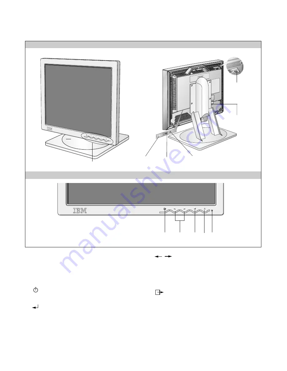
FRONT VIEW
REAR VIEW
Front Control Panel
Front Control Panel
Power Connect
Power ON/OFF
Switch
AUDIO DC OUT
D-sub Siganl Port
DVI Port
3
2
1
4
5
1. Power Indicator
This indicator lights up green when the monitor
operates normally; In DPMS (Energy Saving) mode,
- stand-by, suspend, or power off mode - its color
changes to orange.
2.
Power ON/OFF Button
Switches the monitors on and off.
3.
ENTER Button
1) Displays main OSD menu.
2) Enters highlighted menus and submenus.
3) Selects highlighted option.
4.
Arrow Key
Moves the cursor to highlight icons or make adjustments.
1) Brings up Contrast control OSD.
2) Left and Right arrows pressed together bring up auto
setup.
5.
Exit Button
OSD on
1) Exits from menus, sub menus.
2) Exits from OSD.
OSD off
1) Change the input signals(DVI-I
↔
D-Sub).
Summary of Contents for T860 9494-HWN
Page 20: ...20 3 POWER BOARD Component Side 4 POWER BOARD Solder Side...
Page 22: ...22 EXPLODED VIEW 1 15 16 11 10 a a c b 6 5 7 2 A 8 9 13 12 3 14 4...
Page 35: ...SCHEMATIC DIAGRAM 32 1 GM5020...
Page 36: ...33 2 MEMORY...
Page 37: ...34 3 LVDS...
Page 38: ...35 4 MICOM...
Page 39: ...36 5 DC DC...
Page 40: ...37 6 CONNECTOR...
Page 41: ...38 7 INPUT SWITCHING...
Page 42: ...39 8 CONTROL KEY...
Page 43: ...40 9 POWER...


