


2
1
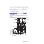
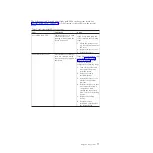
Ethernet
activity LEDs
Locator button/
locator LED
Information LED
System-error LED
Release latch
Power-control button/
power-on LED
Power-control
button cover
Ethernet
icon LED
2.
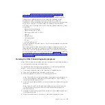
To view the light path diagnostics panel, slide the blue release latch on the
operator panel to the left. Pull forward on the panel until the hinge of the
operator panel is free of the server chassis. Then pull down on the panel so
that you can view the light path diagnostics panel information. This reveals the
light path diagnostics panel. Lit LEDs on this panel indicate the type of error
that has occurred.
Note:
When you slide the light path diagnostics panel out of the server to
check the LEDs or checkpoint codes, do not run the server continuously with
the light path diagnostics panel outside of the server. The panel should only be
outside of the server a short time. The light path diagnostics panel must remain
in the server when the server is running to ensure proper cooling.
The following illustration shows the light path diagnostics panel:
Note any LEDs that are lit, and then reinstall the light path diagnostics panel in
the server.
v
Remind button:
Press this button to place the system-error LED on the front
information panel into Remind mode. By placing the system-error LED
indicator in Remind mode, you acknowledge that you are aware of the last
failure but will not take immediate action to correct the problem. In Remind
mode, the system-error LED flashes rapidly until one of the following
conditions occurs:
– All known errors are corrected.
– The server is restarted.
– A new error occurs, causing the system-error LED to be lit again.
v
NMI button:
The NMI button on the front panel will come on when this
button is pressed. Press this button to force a nonmaskable interrupt to the
microprocessor. You might have to use a pen or the end of a straightened
paper clip to press the button. It allows you to blue screen the server and
take a memory dump (use this button only when directed by the IBM service
support).
68
System x3690 X5 Types 7147, 7148, 7149, and 7192: Problem Determination and Service Guide
Summary of Contents for System x3690 X5
Page 1: ...System x3690 X5 Types 7147 7148 7149 and 7192 Problem Determination and Service Guide...
Page 2: ......
Page 3: ...System x3690 X5 Types 7147 7148 7149 and 7192 Problem Determination and Service Guide...
Page 8: ...vi System x3690 X5 Types 7147 7148 7149 and 7192 Problem Determination and Service Guide...
Page 13: ...Safety statements Safety xi...
Page 22: ...4 System x3690 X5 Types 7147 7148 7149 and 7192 Problem Determination and Service Guide...
Page 266: ...248 System x3690 X5 Types 7147 7148 7149 and 7192 Problem Determination and Service Guide...
Page 278: ...260 System x3690 X5 Types 7147 7148 7149 and 7192 Problem Determination and Service Guide...
Page 386: ...368 System x3690 X5 Types 7147 7148 7149 and 7192 Problem Determination and Service Guide...
Page 407: ...1 2 Chapter 5 Removing and replacing components 389...
Page 444: ...426 System x3690 X5 Types 7147 7148 7149 and 7192 Problem Determination and Service Guide...
Page 454: ...436 System x3690 X5 Types 7147 7148 7149 and 7192 Problem Determination and Service Guide...
Page 461: ...weight of memory enclosure 28 Index 443...
Page 462: ...444 System x3690 X5 Types 7147 7148 7149 and 7192 Problem Determination and Service Guide...
Page 463: ......
Page 464: ...Part Number 47C8865 Printed in USA 1P P N 47C8865...