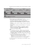
The following table shows the DIMM configurations that are supported for the dx360
server.
Table 2. Supported DIMM configurations
Branch 0
Branch 1
Channel A
Channel B
Channel C
Channel D
A1 A2 A3 A4 B1 B2 B3 B4 C1 C2 C3
C4 D1 D2 D3 D4
X
X
X
X
X
X
X
X
X
X
X
X
X
X
X
X
X
X
X
X
X
X
X
X
X
X
X
X
X
X
Legend:
X
Slot is populated: Supported configuration.
Slot is not populated.
DIMM slot population rules for the dx360 server are as follows:
v
Within a branch, DIMMs must be populated in slot order starting with Slot 1 for
each channel, followed by slot 2, then slot 3, and ending with slot 4.
v
DIMMs must be populated in matching pairs across channels within a given
branch. Therefore, when populating DIMM pairs, the population order would be
as follows:
A1 and B1; C1 and D1; A2 and B2; C2 and D2; A3 and B3; C3 and D3; A4 and
B4; C4 and D4
v
DIMMs that make up a given pair must match with respect to size, speed, and
organization.
v
DIMM size can vary from one DIMM pair to another, however, speed and
organization must be the same. For example, DIMM Pair A1 and B1 are
populated with x8 1GB DDR2-667 DIMMs. DIMM Pair C1 and D1 can be
populated with x8 2GB DDR2-667 DIMMs.
Notes:
1. For best performance, the number of DIMMs installed should be balanced
across both memory branches. For example, a four DIMM configuration will
perform better than a two DIMM configuration and should be installed in DIMM
Slots A1, B1, C1, and D1. An eight DIMM configuration will perform better than
a six DIMM configuration.
2. The minimum memory upgrade increment is two DIMMs per branch. The DIMM
options that are available for the server are 2 GB and 4 GB.
v
DIMMs must cover the same slot position on both channels.
v
DIMM pairs must be identical with respect to size, speed, and organization.
v
DIMMs that cover adjacent slot positions do not need to be identical.
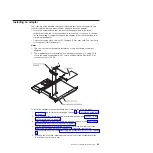
The following illustration shows the dual inline memory module (DIMM) connectors
on the system board.
Chapter 3. Installing optional devices
27
Summary of Contents for System x iDataPlex dx360
Page 1: ...System x iDataPlex dx360 Types 6313 6316 6385 6390 7831 and 7833 User s Guide...
Page 2: ......
Page 3: ...System x iDataPlex dx360 Types 6313 6316 6385 6390 7831 and 7833 User s Guide...
Page 11: ...Statement 10 CAUTION Do not place any object on top of rack mounted devices Safety ix...
Page 12: ...x IBM iDataPlex dx360 User s Guide...
Page 46: ...34 IBM iDataPlex dx360 User s Guide...
Page 54: ...42 IBM iDataPlex dx360 User s Guide...
Page 67: ......
Page 68: ...Part Number 90Y5678 Printed in USA 1P P N 90Y5678...


