background image

4.


Plug


the


network


ethernet


cable


2


in


Figure


1-12


on


page


1-10


or


Figure


1-13


on


page


1-10)


into


the


ethernet


port


on


the


back


panel


of


the


library.


If


the


ethernet


connection


is


directly


attached


to


a


server


or


laptop,


a


crossover


ethernet


cable


may


be


required.

Installing


a


Fibre


Channel


Interposer


(Feature


Code


5096)


For


a


list


of


supported


adapters


and


required


interposers,


go


to


the


Technical


Support


section


on


the


web


at


http://www.ibm.com/storage/lto.
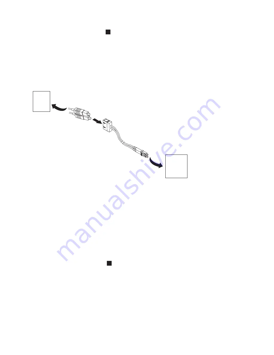
 

To


install


the


interposer,


refer


to


Figure


1-14


and


the


procedure


below.


1.


Connect


the


host


SC


fibre


cable


to


the


matching


side


of


the


interposer.


2.


Connect


the


drive


LC


fibre


side


of


the


interposer


to


the


drive/library.

Connecting


a


Power


Cord


Attention:


This


product


can


ONLY


be


used


with


an


approved


power


cord


for


your


specific


geographic


region.


Use


of


an


unapproved


power


cord


may


result


in:


v


not


meeting


individual


country


specific


safety


requirements;


v


overheating


with


potential


personal


injury


and/or


property


damage;


and


v


a


fracture


resulting


in


the


internal


contacts


being


exposed,


which


potentially


could


subject


the


user


to


a


shock


hazard.

1.


Plug


one


end


of


the


power


cord


(

4


in


Figure


1-12


on


page


1-10


or


Figure


1-13


on


page


1-10)


into


the


power


connector


on


the


back


panel


of


the


library.


2.


Plug


the


other


end


of


the


power


cord


into


the


nearest


properly


grounded


power


outlet.


Attention:


To


disconnect


all


power


from


the


library,


remove


the


power


cord


from


the


outlet.


The


power


button


only


puts


the


power


on


stand-by.


3.


Turn


ON


the


library


using


the


power


button.


Check


the


Operator


Control


Panel


display


to


make


sure


the


library


is


receiving


power.


If


it


is


not,


check


the


power


connections


and


your


power


source.


During


the


Power-On


Self


Test


(POST),


all


four


LEDs


are


illuminated


briefly,


followed


by


a


flashing


Ready


LED.


When


the


initialization


sequence


is


complete,


the


Home


screen


will


be


displayed.

a67m0276

Host

Fibre

Channel

Network

Library

Fibre

Channel

Drive

Connector

11P1373


Figure


1-14.


Interposer


installation


Installation


1-11

Summary of Contents for System Storage TS3100

Page 1: ...IBM System Storage TS3100 Tape Library and TS3200 Tape Library Installation Quick Reference Machine Type 3573 GA32 0548 00...

Page 2: ......

Page 3: ...IBM System Storage TS3100 Tape Library and TS3200 Tape Library Installation Quick Reference Machine Type 3573 GA32 0548 00...

Page 4: ...at http www ibm com storage lto Second Edition June 2006 This edition applies to the IBM System Storage TS3100 Tape Library and TS3200 Tape Library Installation Quick Reference GA32 0548 00 and to the...

Page 5: ...the Library for Rack Installation ONLY 1 4 Attaching the Library to a Server 1 9 Connecting the Host Interface Cable 1 9 Connecting a Power Cord 1 11 Preparing the Host 1 12 Verifying the Connection 1...

Page 6: ...iv TS3100 and TS3200 3573 Installation Quick Reference...

Page 7: ...ople because of some existing condition The following are examples of caution notices A hazardous electrical condition with less severity than electrical danger A generally hazardous condition not rep...

Page 8: ...led in a different rack cabinet v An electrical outlet that is not correctly wired could place hazardous voltage on the metal parts of the system or the devices that attach to the system It is the res...

Page 9: ...e that the four leveling pads are raised to their highest position v Ensure that there is no stabilizer bracket installed on the rack cabinet during movement v Do not use a ramp inclined at more than...

Page 10: ...ironment and human health due to the potential presence of hazardous substances in EEE For proper collection and treatment contact your local IBM representative Battery Return Program This product may...

Page 11: ...nches v Sides Minimum of 5 08 cm 2 inches Rack requirements Standard 19 inch rack with v 2U 63 5 mm 3 5 in of clearance for a 2U library v 4U 177 8 mm 7 in of clearance for a 4U library Rackmounting t...

Page 12: ...nal item that is included in your shipment if ordered Rack Mount Kit Important If any of the contents of your shipment are damaged or missing please call the appropriate number listed on the Quality H...

Page 13: ...ON The shipping lock is held in place with a label and is located in the top center of the library After the shipping lock is removed it should be stored on the right side of the back panel of the li...

Page 14: ...ndard 19 inch rack system The 2U library requires 2U 3 5 in of space The 4U library requires 4U 7 in of space If you are not rackmounting your library skip this procedure and go to Attaching the Libra...

Page 15: ...install your library in a rack perform the following steps 1 Verify that your rack kit includes the following contents see Figure 1 4 v Packaged in plastic material 2 rails 2 mounting brackets v Packa...

Page 16: ...front and back of each rail to the rack The rails extend to fit a variety of rack depths Each rail requires 2U of rack space 1 in Figure 1 5 4 Using the Torx wrench included in your shipment remove t...

Page 17: ...ith library rack anchors and mounting brackets installed slide the library onto the rails as shown in Figure 1 8 and Figure 1 9 on page 1 8 When the library stops gently push the library to lock the a...

Page 18: ...e Figure 1 11 on page 1 9 for a 4U library by placing a screw in the center hole of each mounting bracket and tightening them 1 a77ug109 Figure 1 9 Sliding the 4U library into the rack a77ug112 1 Figu...

Page 19: ...the server and all attached accessories Important Failure to remove the power cords from these devices before connecting the host interface cable could result in damage to the library 2 For a SCSI lib...

Page 20: ...cables and terminators specified for Ultra160 or Ultra320 use or labeled as Multi Mode should be used Note The host bus adapter should be LVD SCSI A single ended SE SCSI host bus adapter will work bu...

Page 21: ...requirements v overheating with potential personal injury and or property damage and v a fracture resulting in the internal contacts being exposed which potentially could subject the user to a shock h...

Page 22: ...erminated Likewise if the library is physically the last SCSI device on the SCSI bus it must be terminated Only the devices physically located at the beginning and end of the SCSI bus should be termin...

Page 23: ...ol as your library network setting complete Steps 1 2 3 and 7 If you do not want to use DHCP as your library network setting complete Steps 1 2 4 5 6 and 7 1 Press the DOWN button to highlight the Net...

Page 24: ...1 18 6 Entering Date and Time using the Web User Interface on page 1 18 7 Entering Control Path Failover License Activation Key on page 1 19 8 Configuring Logs and Traces using the Web User Interface...

Page 25: ...ge in any order Sequential In sequential mode the library s firmware predefines the selection of the cartridges After initialization the firmware causes the library to select the first available cartr...

Page 26: ...r each drive listed either SCSI or Fibre Channel Refer to Figure 1 19 on page 1 17 3 Click one of the following v Refresh to update the current screen v Submit to apply the changes made to the screen...

Page 27: ...dress Network Mask and Gateway Address IP Address An identifier for a computer or device on a TCP IP network Networks using the TCP IP protocol route messages based on the IP address of the destinatio...

Page 28: ...Access PIN Code enter the personal identification number again 8 In Support Name enter the name of the person that will be able to offer the user help with the library 9 In Support Phone enter the pho...

Page 29: ...races using the Web User Interface This function is not available on the Operator Control Panel 1 Click Logs Traces in the left navigation pane 2 It is recommended that you select Continuous so all in...

Page 30: ...like to be notified when a warning occurs select Notify Warnings 3 In To Email Address enter the email address to which the information will be sent 4 In Email Domain enter the domain name for the ema...

Page 31: ...l Panel on page 1 23 8 Restoring Factory Default Settings using the Operator Control Panel on page 1 23 Choosing the Number of Logical Libraries 1 Navigate to Configure Logical Libraries 2 Press the D...

Page 32: ...the Netmask field b Press the UP or DOWN button to select the digit s in your library s Netmask address c Press the ENTER button to highlight the next digit s in your library s Netmask address d Afte...

Page 33: ...After entering the final digit press the DOWN button and select one of the following v Save to apply your settings v Cancel to delete your settings Restoring Factory Default Settings using the Operat...

Page 34: ...t magazine To open the I O Station select Control Open I O Station The I O Station will pop open To close the I O Station gently push it back into the left magazine a77ug020 Figure 1 27 2U library lef...

Page 35: ...rage slots The lower left magazine has nine storage slots and houses the 3 slot I O Station 1 in Figure 1 30 on page 1 26 The upper right magazine has twelve storage slots The lower right magazine has...

Page 36: ...a77ug105 1 Figure 1 30 4U library left magazines 1 26 TS3100 and TS3200 3573 Installation Quick Reference...

Page 37: ...n page 1 28 is part of the lower left magazine To open the I O Station select Control Open I O Station The I O Station will pop open To close the I O Station gently push it back into the lower left ma...

Page 38: ...e Library with Data Cartridges For information on working with the cartridge magazines see Cartridge Magazines on page 1 23 1 Unlock the cartridge magazines a77ug103 Figure 1 32 4U library I O Station...

Page 39: ...CS This slot holds the cleaning cartridge In a 2U library the cleaning cartridge can be placed in any storage slot With the Auto Clean feature enabled a drive will be cleaned automatically when necess...

Page 40: ...1 30 TS3100 and TS3200 3573 Installation Quick Reference...

Page 41: ...ied Very Dissatisfied Accurate h h h h h Complete h h h h h Easy to find h h h h h Easy to understand h h h h h Well organized h h h h h Applicable to your tasks h h h h h Please tell us how we can im...

Page 42: ...pment Department GZW 9000 South Rita Road Tucson Arizona U S A 85775 4401 _ _ _ _ _ _ _ _ _ _ _ _ _ _ _ _ _ _ _ _ _ _ _ _ _ _ _ _ _ _ _ _ _ _ _ _ _ _ _ _ _ _ _ _ _ _ _ _ _ _ _ _ _ _ _ _ _ _ _ _ _ _ _...

Page 43: ......

Page 44: ...Part Number 23R7508 Printed in USA GA32 0548 00 1P P N 23R7508...

Page 45: ...Spine information IBM System Storage TS3100 Tape Library and TS3200 Tape Library TS3100 and TS3200 3573 Installation Quick Reference Machine Type 3573...

Reviews: