If the power sources have circuit breakers or switches, ensure that they are turned on. The enclosure
does not have power switches. Repeat this step for each expansion enclosure in the system.
Note: Each enclosure has two power supply units. To provide power failure redundancy, connect the
two power cords to separate power circuits.
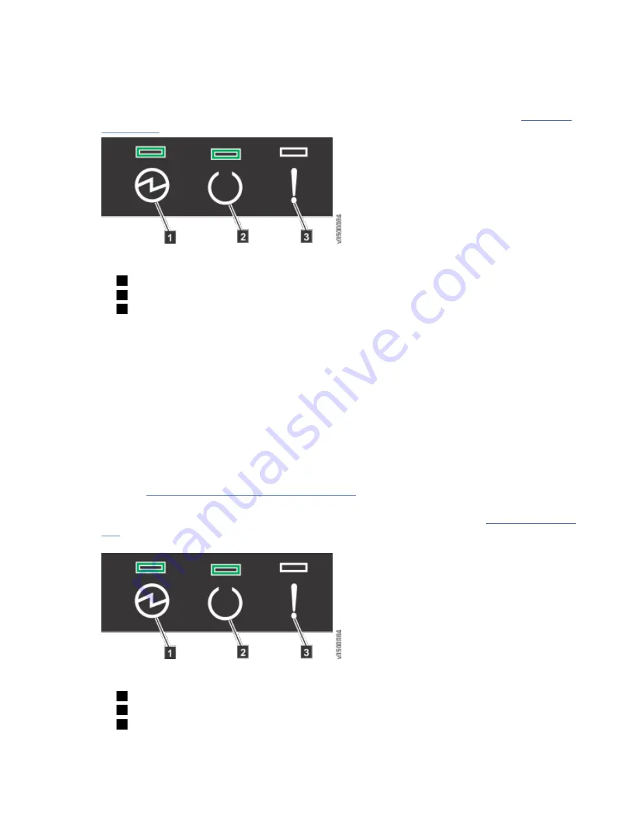
2. From the rear of the expansion enclosure, check the LEDs on each expansion canister (see Figure 140
Figure 140. Expansion canister LEDs
1
Power
2
Status
3
Fault
The canister is ready with no critical errors when Power is illuminated, Status is on, and Fault is off. If
a canister is not ready, refer to the "Procedure: Understanding the system status using the LEDs" topic
in "Troubleshooting".
3. Wait for all expansion canisters to finish powering on.
4. Power on the control enclosure. Use the supplied power cords to connect both power supply units of
the enclosure to their power sources.
If the power sources have circuit breakers or switches, ensure that they are turned on. The enclosure
does not have power switches.
Notes:
• Each enclosure has two power supply units. To provide power failure redundancy, connect the two
power cords to separate power circuits.
• Review the information on securing the power cables to ensure that each power cable is secured to
each PSU on the back of the enclosure.
5. From the rear of the control enclosure, check the LEDs on each node canister. (See Figure 141 on page
128.)
Figure 141. Node canister LEDs
1
Power
2
Status
3
Fault
128 Storwize V5000 Gen2: Quick Installation Guide
Summary of Contents for Storwize V5000 Gen 2 Series
Page 1: ...IBM Storwize V5000 Gen2 Quick Installation Guide IBM...
Page 5: ...Index 149 v...
Page 6: ...vi...
Page 156: ...130 Storwize V5000 Gen2 Quick Installation Guide...
Page 164: ...138 Storwize V5000 Gen2 Quick Installation Guide...
Page 166: ...140 Storwize V5000 Gen2 Quick Installation Guide...
Page 168: ...142 Storwize V5000 Gen2 Quick Installation Guide...
Page 177: ......
Page 178: ...IBM...


