Options applicable to expansion enclosures:
__
v
Expansion enclosure attachment cables
__
v
Drives
__
v
Power cords for connection to wall sockets
Identifying the hardware components
The following graphics and descriptions identify the various hardware components
and port locations for the control enclosure and expansion enclosure.
Control enclosure components
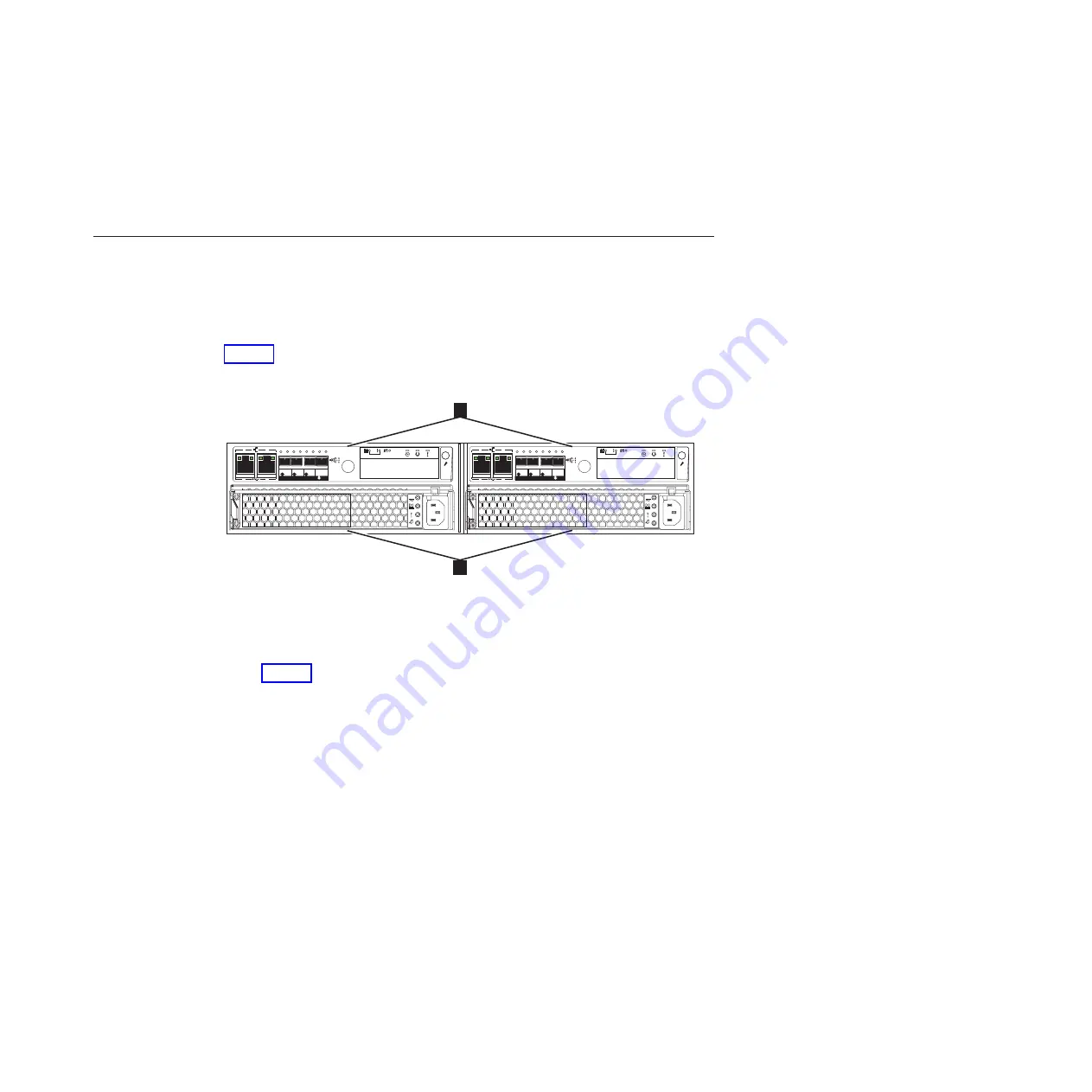
Figure 1 shows the rear view of a control enclosure and identifies the location of
the power supply units and node canisters.
v
1
Node canisters
v
2
Power supply units
Note:
Figure 1 shows the node canisters in their initial configuration, with no host
interface card options installed.
v35001
12
1
2
1
2
1
2
OK
IN
1
2
3
4
6
1
2
1
2
OK
IN
1
2
3
4
6
Figure 1. Rear view of a Storwize V3700 control enclosure
Chapter 1. Before you begin the installation
5
Summary of Contents for Storwize V3700
Page 1: ...IBM Storwize V3700 Quick Installation Guide GC27 4219 01...
Page 4: ...iv Storwize V3700 Quick Installation Guide...
Page 6: ...vi Storwize V3700 Quick Installation Guide...
Page 8: ...viii Storwize V3700 Quick Installation Guide...
Page 14: ...xiv Storwize V3700 Quick Installation Guide...
Page 30: ...10 Storwize V3700 Quick Installation Guide...
Page 64: ...44 Storwize V3700 Quick Installation Guide...
Page 78: ...f2c00790 58 Storwize V3700 Quick Installation Guide...
Page 81: ......
Page 82: ...Part Number 00AR171 Printed in USA GC27 4219 01 1P P N 00AR171...


